
تبلیغات
موضوعات
جستجو
پیوندهای روزانه
لینک دوستان
- دریافت رایگان این قالب
- سایت عاشقانه ماندگار فان
- سایت عاشقانه عشق آفرین
- جامعه رادیو اماتوری ایران
- سازمان تنظيم مقررات و ارتباطات راديوئي
- شرکت اروم الکترونیک
- فروشگاه قطعات الكترونيكي
- ARRL • Devoted Entirely to Amateur Radio
- درددل های یک بازنشسته
- نخستین سایت آموزشی رادیو آماتوری در ایران
- نشریات آماتوری
- EP2MRD
- QRZCQ - The database for radio hams
- شناسه تخصيص نحوه دستورالعمل ايستگاه به ارتباط راديويي هاي ) Call Sign ( دستورالعمل ارتباط شناسه تخصيص نحوه ايستگاه به راديويي
- رادیو آماتوری
- کلوپ رادیو آماتوری ایرانیان
- ارسال لینک
صفحات جانبی
امکانات جانبی
 آمار
وب سایت:
آمار
وب سایت:
بازدید دیروز : 4890
بازدید هفته : 16080
بازدید ماه : 28989
بازدید کل : 2529080
تعداد مطالب : 675
تعداد نظرات : 121
تعداد آنلاین : 1
.jpg)


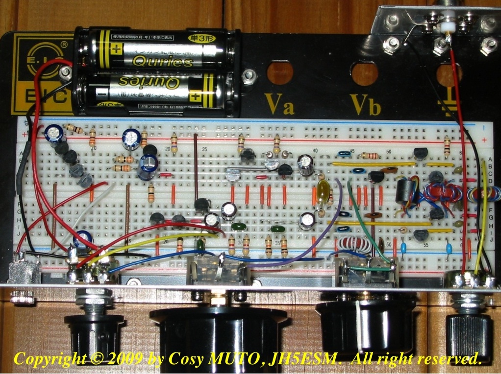
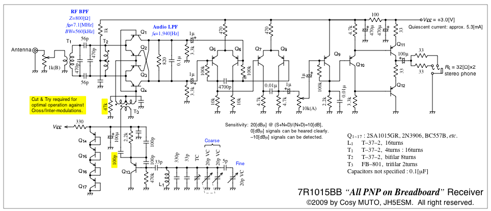
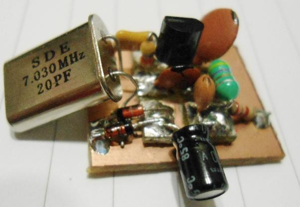
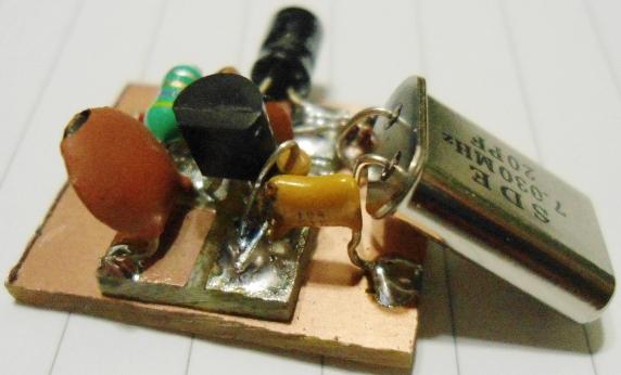
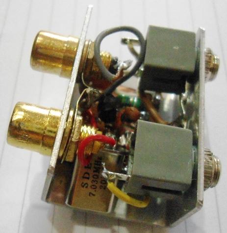
7mhz pnp
A direct conversion receiver for 7MHz only made of single kind of general purpose PNP transistor is presented. No other semiconductor devices (even diodes!) are used. The circuit is built on a solderless breadboard so that it is easy to build, repair and modify it.
.jpg)

Ten Minute Transmitter
با تسلیت فرارسیدن ایام شهادت حضرت محمد (ص) و امام سجاد(ع) و امام رضا (ع)
Last weekend I was browsing the internet for radio circuits and came across an interesting design I've never seen before, nicknamed the Ten Minute Transmitter. The design apparently originated in 1996 in an amateur radio club QRP publication. The name originates since the original author claimed he built this transmitter and make a QSO with it in just 10 minutes time. Impressive!
I didn't set a stopwatch to time myself, but I can tell you that I was able to slap this rig together on a breadboard and tune it up very quickly. There are no coils to wind (unless you want to); it tunes a wide range of crystal frequencies, and it outputs an easy 500mW AM signal. I had three crystals on hand, and was able to load up frequencies 6925 kHz, 14322 kHz and 28266 kHz without problem.
Here's the schematic:
![]()
short wave listener
شنیدن صدای کوتاه و یا SWLing، سرگرمی گوش دادن به پخش های رادیویی مجهز به فرکانس بین 1700 تا 30 مگاهرتز است.
[1] شنوندگان از کاربران معمولی به دنبال برنامه های بین المللی اخبار و سرگرمی، سرگرمی ها در جنبه های فنی پذیرش رادیو و جمع آوری تاییدیه های رسمی (کارت QSL) است که دریافت پیام های از راه دور (DXing) را ضبط می کنند.
در بعضی از کشورهای در حال توسعه، گوش دادن به میکروفون، جوامع دور افتاده را قادر می سازد
برنامه های منطقوی را که به طور معمول توسط رسانه های پخش کننده محلی AM پخش می شود، دریافت کنند.
برآورد یک برآورد سال 2002 تعداد صدها نفر از شنوندگان مجهز به صداهای مختلف را در صدها میلیون نفر قرار داد. تمرین گوش دادن به رادیو از راه دور در دهه 1920 آغاز شد، زمانی که شرکت های مخابراتی کوتاه مدت در ایالات متحده و اروپا تاسیس شد.
مخاطبان متوجه شدند که برنامه های بین المللی در باند های کوتاه مدت بسیاری از گیرنده های رادیو مصرف کننده در دسترس بوده است و تعدادی از مجلات و باشگاه های شنوایی که به این عمل مشغول هستند، به نتیجه رسیدند.
گوش دادن به Shortwave به خصوص در زمان جنگ بین المللی مانند جنگ جهانی دوم، جنگ کره و جنگ خلیج فارس بسیار محبوب بود. شنوندگان از گیرنده های رادیویی قابل حمل "دنیای دیجیتال" ارزان قیمت برای دسترسی به باندهای کوتاه مدت استفاده می کنند و برخی از سرگرمی های پیشرفته از گیرنده های ارتباطی تخصصی با تکنولوژی دیجیتالی طراحی شده برای دریافت سیگنال های کوتاه مدت و همچنین آنتن های خارجی برای افزایش کارایی استفاده می کنند. با ظهور اینترنت، بسیاری از پخش کننده های بین المللی، پیامدهای کوتاه مدت خود را به نفع توزیع برنامه های مبتنی بر وب کاهش داده اند، در حالی که دیگران از حالت های آنالوگ به دیجیتال دیجیتال حرکت می کنند تا امکان پخش برنامه های کوتاه مدت را فراهم کند.
تعدادی از باشگاه های گوش دادن به اینترنت در کوتاهترین زمان همراه با مجلات چاپی اختصاص یافته به سرگرمی کاهش یافته است؛ با این حال، علاقه مندان بسیاری به تبادل اطلاعات و اخبار در وب ادامه می دهند.
radio amateur books
ادرس فوق شامل کتب و مطالب جالبی است برای دوستان رادیو اماتور و لیست کامل در ادامه مطلب می باشد
http://www.n5dux.com/ham/files/pdf
رادیو گیرنده موج کوتاه لامپی
با سلام
طرح ضمیمه رادیو تک لامپ گیرنده موج کوتاه است که با برق ضعیف کار کرده و خطر برق گرفتگی ندارد

![]()
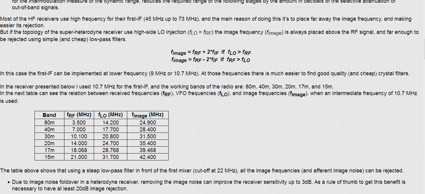
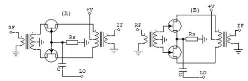
Low Noise Floor SSB Transceiver for 80m to 15m
با سلام و ارزوی قبولی طاعات و عبادات و تبریک پیروزی تیم ملی فوتبال و راهیابی ایران به جام جهانی
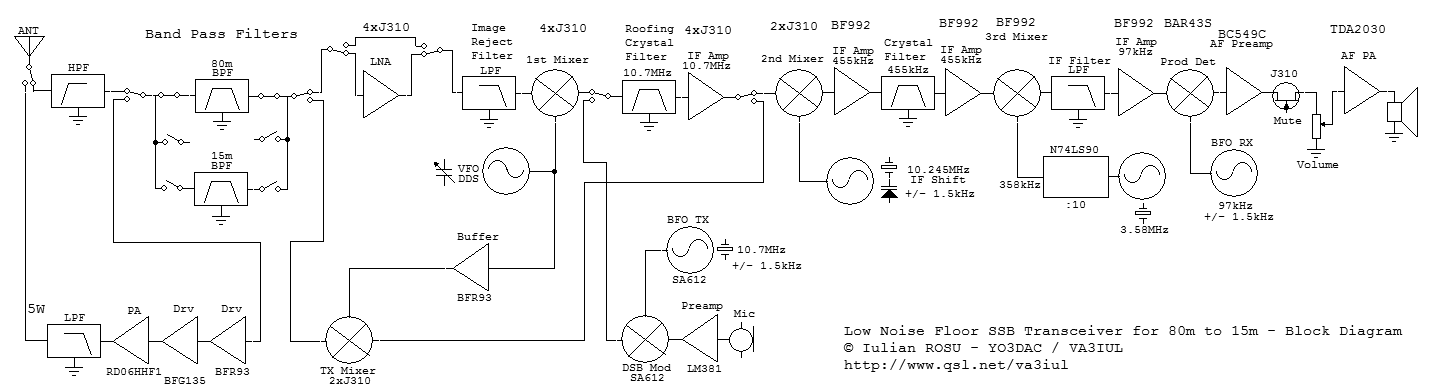

توضیحات در ادامه مطلب
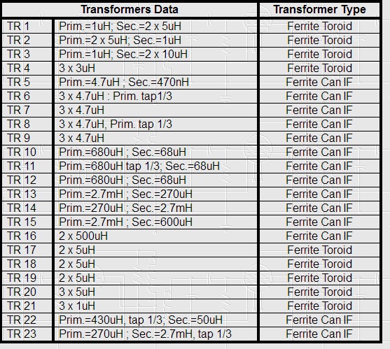
20m Loop Antenna
با سلام
http://213.114.137.49/antennas/20m_ant_00.htm
by Harry Lythall - SM0VPO
این رادیو اماتور عزیز در کشورخودشن سوئد در اپارتمان زیر در طبقه چهارم زندگی می کند و بسیار علاقمند به تماس در باند 20 متر بودند
با توجه به محدودیت های موجود ایشون تصمیم گرفتند با امکانات موجود یک انتن ساده برای تماس در 14 مگا بسازند
لوازمی که مورد نظرشون بود عبارت بود از یکمتر لوله 15 میلیمتری پلاستیکی که برای کابل کشی درون ساختمان استفاده می شود و چند متر سیم برق نمره2/5
برای این کار ابتدا طول هرلوله 80 سانتیمتر جدا کرده و بعد از بستن انها بهم دیگر بصورت صلیب لوله ها را بافاصله 4 سانتیمتر از هم و 3دور برای سیم پیچ خروجی با فاصله یک سانت از نوک لوله سوراخ کردم در نتیجه فاصله سیم پیچ از هم 2/5 سانتیمترشد در یک سمت لوله عمودی با همان فاصله نیم دور سیم با اضافه کردن دو سوراخ چهارم جهت تغذیه از فرستنده قراردادم
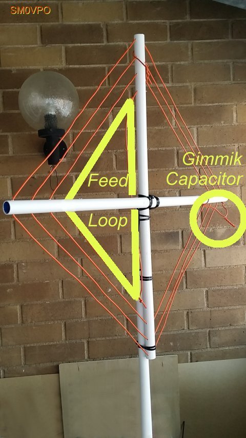
بعد از نصب قطعات نقطه کار انتن بصورت اماده در 14900 کیلو بدست امد و برای تنظیم دقیق انتن در انتهای سیم های بیرونی مقداری از سیم ها را دور هم پیچیدم تا خازنی تهیه شود که با تنظیم دقیق مقدار دور هم پیچیده شده فرکانس کار پایین امده و به 14175 رسید
سر راه 5متر کابل انتنrg58 و انتن لوپ با استفاده از توروئید بکار رفته در منابع تغذیه کامپیوتر و سه رشته سیم با قطر یک میلیمتر تعداد 7 دور سیم بهم بافته را رد کرده و سر سیم هارا سری به هم وصل کردم
اول سر سیم الف بعد ته سیم الف به سر سیم ب بعد ته سیم ب به سر سیم ج و در اخر ته سیم جیم که به ترتیب شماره 1 و 2 و 3 و 4 شماره می گیرند
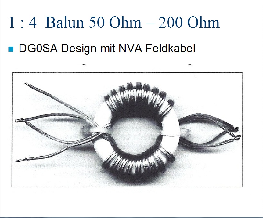
مطابق شکل زیر سیم ها به بالون متصل می شوند
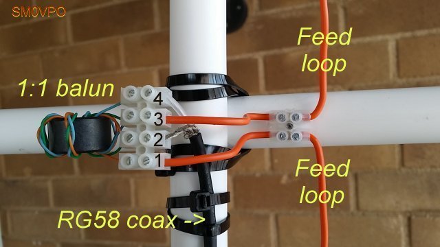
دو سر سیم تغذیه لوپ به اتصال یک و سوم وصل می شود مغزی کابل به سر چهار و بدنه کابل به سر دو اتصال خواهد داشت
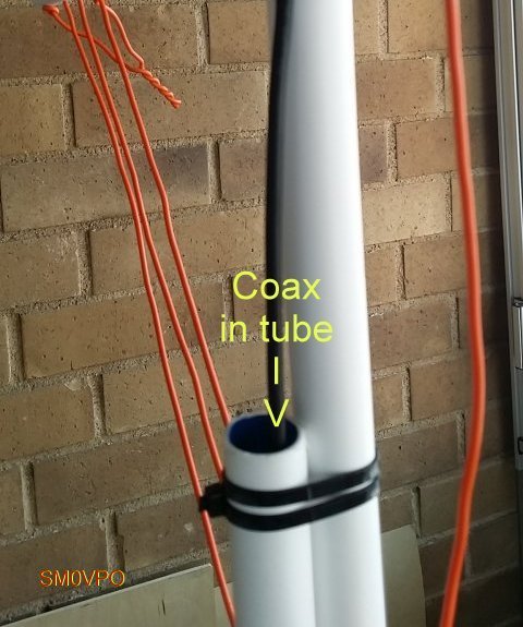
کابل انتن هم از درون لوله نگهدارنده انتن لوپ عبور داده می شود
ابتدا و انتهای سه دور سیم لوپ را کمی بلند گرفته تا بروی هم تابیده شده و تشکیل خازن قابل تنظیم بدهند
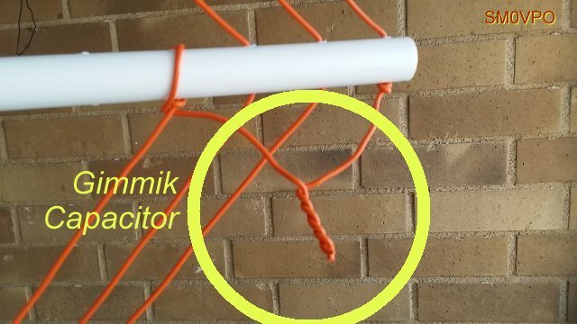
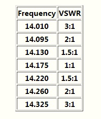
بعد با یک انتن انالایزر یا گرید دیپ متر یا برگشت سنج این تابیدگی را طوری انجام میدهیم که حداقل برگشت را در فرکانس 14175 کیلوهرتز داشته باشیم و انتن تنظیم و طول اضافه بریده و انتن اماده کار است
اصل گزارش در ادامه مطلب:
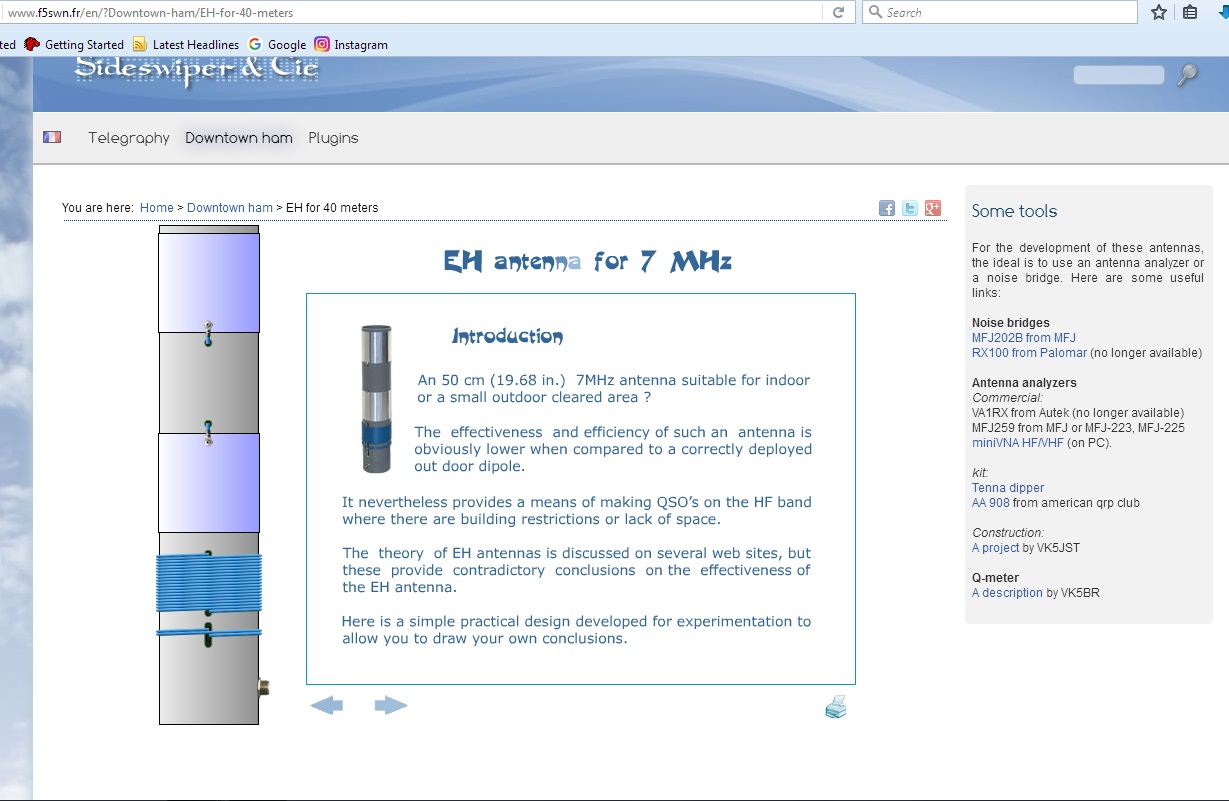
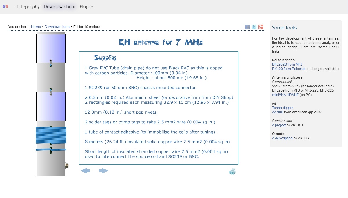
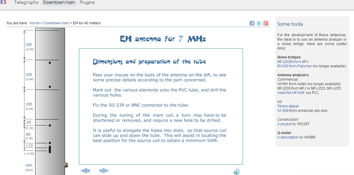
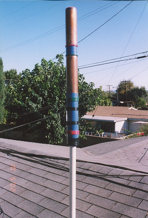
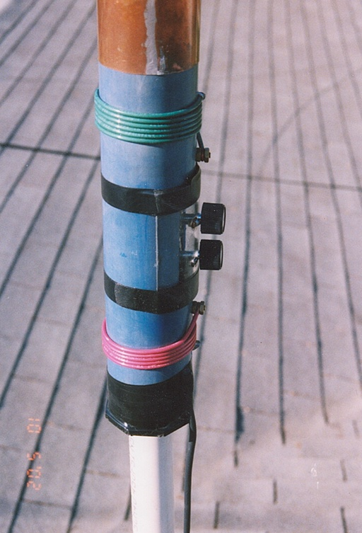
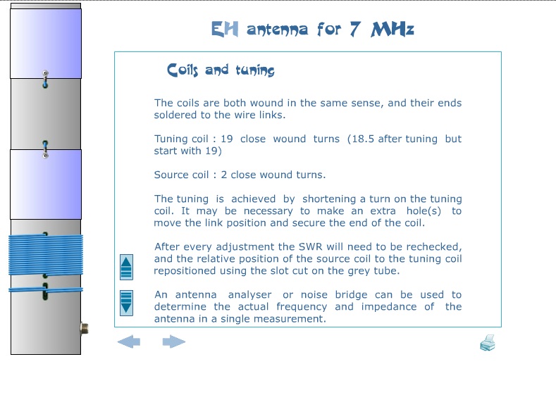
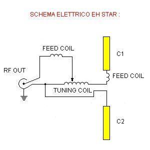
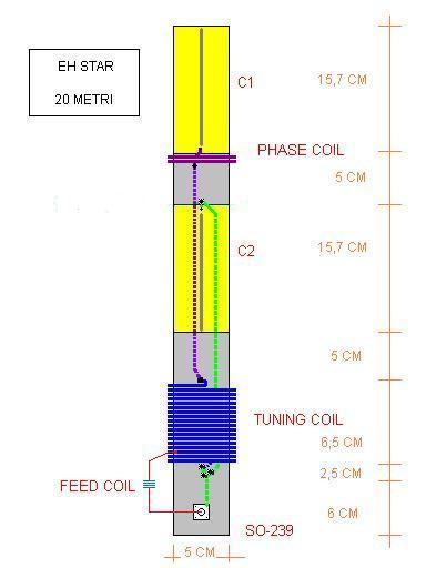
EH STAR (14 Mhz)
با سلام
این نوع انتن ها با اندازه بسیار کوتاه و انتشار ورتیکال و جای کم و. ساخت راحت ایده ال برای کار در اپارتمان و ساختمان های شهری هستند
http://iw3hzx.altervista.org/Antenne/EHSTAR/Ehstar.htm
توضیح در ادامه مطلب:
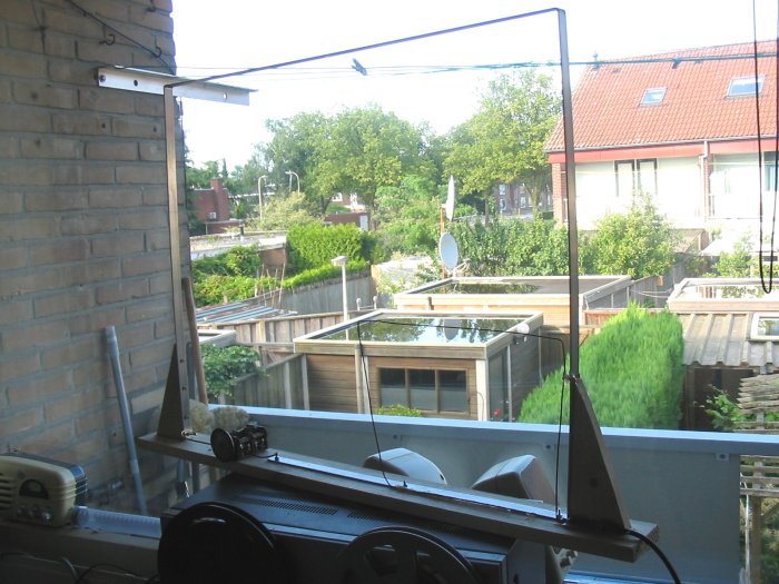
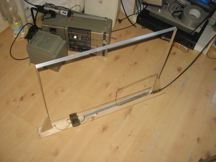
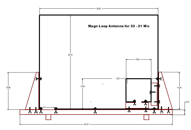
QRP Indoor Loop
QRP Indoor Loop
For QRP operation with limited space, a compact and lightweight 'magnetic' loop antenna was built. For the first design (which leaves room for improvement), a long thin piece of aluminium sheet was used (3.14 meters total circumfence, 50 mm wide, 2 mm thickness)
.jpg)
Unlike most classic loop designs, the tuning capacitor and the smaller coupling loop are both at the base of the antenna. The tuning capacitor with approximately 20 ... 250 pF should be replaced with a 'butterfly'-design, but these are either difficult to find or too expensive, so a 'normal' variable capacitor scrapped from an old antenna tuner was used. With this arrangement, the resonant tuning range was 7 to 21 MHz. With a "better" capacitor (lower minimum capacity), tuning above 21 MHz could be easier.
.jpg)
The small neon lamp on the right side of the capacitor initially acted as a tuning aid. One of its legs is connected to the outer loop, the other leg is only capacitively coupled to the other electrode of the tuning capacitor. It later turned out that adjusting the loop for resonance 'by ear' brings the SWR low enough before transmitting (at QRP levels!), the 'fine tuning' should be done with an SWR meter.
The coupling loop's optimum length (circumfence) was found to be 0.6 meters, which is roughly 1/5th of the outer loop's circumfence, which agrees with many other 'magnetic loop recipes' (for example Rothammel's Antenna Book).
Note that unlike other designs, the small coupling loop of this antenna does not touch the larger outer loop ! If it would, the only point where both loops may touch would be the topmost point, which is 'electically neutral' (voltage minimum of the outer loop).
Due to the lack of an electric connection between the loops, there is also no need for a balun !
.jpg)
The plastic 'insulator' at the bottom holds both loops, and the tuning capacitor in place. The entire loop (including insulator) can be rotated on the wooden base, using a single screw visible in the center of the last photograph.
To eliminate the need for a vernier drive, and to stay away from the tuning capacitor, an plastic lever is used to operate it.
Ideas / possible improvements
The electric conductance of the aluminium loop (measured at DC by passing 2 amperes through the loop, and measuring the voltage - 3 mV - across the loop close to its ends) was found larger than it should have been. Calculation:
       sigma = ( Current * Length ) / ( Voltage * Conducting_Area )
   here:
       sigma = ( 2 A  *  3 m ) / ( 0.003 V * 0.002 m * 0.05 m ) = 20 * 10^6 Siemens / meter

     (In Germany, 'sigma' [σ] denotes the electrical conductance.
      In the English literature, 'kappa' [κ] seems more common.)
The electrical conductivity of pure aluminium would be 36.6 Mega-Siemens per meter; and a loop made of pure copper would be even better (sigma = 58 Mega-Siemens per meter).
Since most of the HF current only flows in the outer few micrometers of the conductor, the loop doesn't have to be "solid". A loop made of a long (bent) piece of plastic, carrying a long strip of copper foil (say 70 micrometers thick, and 50 mm wide) would be even lighter than this loop. Experimentation will tell if the reduced loss in the loop is worth the effort, considering the loss in the capacitor. A thin copper loop in combination with a 'butterfly' capacitor, or -even better- a variable vacuum capacitor will help to cut the losses in the loop even further. But at some point losses in the vincinity of the loop (walls, floors, ceilings, eddy currents in metal objects, etc) will dominate, and it possibly doesn't pay off to reduce the losses in the antenna itself.
http://www.qsl.net/dl4yhf/qrp/index.html#indoor_loop
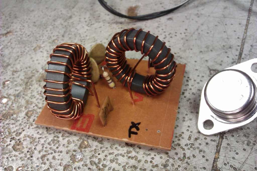
HF swr meter(new)
با سلام و ارزوی سلامتی و موفقیت همه دوستان رادیوآماتور بمناسبت روز جهانی رادیو
در مجله الکتور ژانویه1980 مطلبی بود که برایم جالب بود در یک مدار برگشت سنج از یک پل نمونه گیر با هسته توروئید استفاده کرده بود و لذا حساسیت را در اچ اف بحد میلی وات رسانده و خیلی خوب شده بود
اصل مطلب مجله جهت اطلاع علاقمندان ضمیمه می گردد
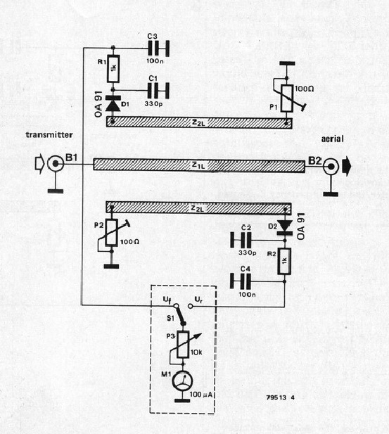
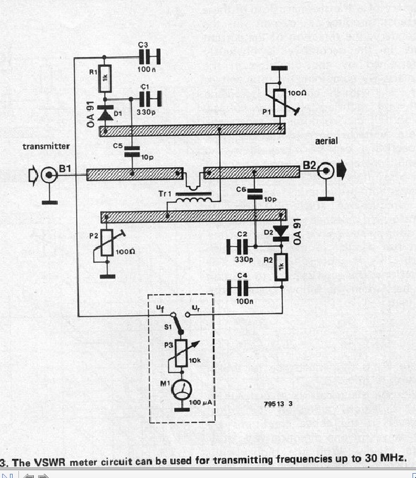
متن کامل مجله در ادامه مطلب
HF swr meter
با سلام و تبریک ایام
Barry Zarucki M0DGQ مدار قدرت سنج و برگشت سنجی را برای باند اچ اف طراحی کرده اند که از 10 تا یک کیلو وات را اندازه گیری می کند برای رنج 200 وات از دو عدد توروئیدFT50-43 استفاده شده و برای رنج یک کیلو وات از 6 عدد توروئیدFT114-43
مدار ساده است و توضیحات عکس ها کامل است در صورت علاقه ادرس مطلب نیز درج می شود:
http://www.m0dgq.co.uk/HF%20swr%20meter.html

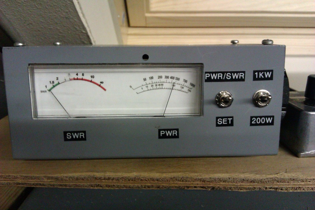

Calibration was done with a Bird meter for comparison, however a diode probe can be used with a DVM using the formula P = Vrms X Vrms / Rload. In other words power in Watts into a 50 Ohm dummy load = Vrms squared divided by 50. The values for resistors R1 and R2 were found by initially using a 100K trimmer and adjusting for correct power reading during calibration, these were then substituted by fixed resistors.
انتن لوپ
با سلام
انتن لوپ قابل استفاده در بالکن و داخل فضای محدود
http://members.home.nl/radiomorningstar/loop.htm
144Mhz radio
video : http://www.youtube.com/watch?v=8SofWPlKgPw
با سلام و تبریک هفته وحدت و میلاد مسعود رسول رحمت
2SC2999 150mw 750mhz 30ma
2SC2786 600mhz 250mw 20ma
2SC1923 550mhz 100mw 20ma
2SC1674 600mhz 250mw 20ma
2N2369 metalico pulso 0,68w 200ma 500mhz
BF224 600mhz 1w 50ma
BF198 400mhz 25ma 0,5w
BF240 1,1ghz 50ma 350mw
BFW16 1,2 ghz 1,5w 150ma rf catv ==>PA
BFY90
2SC2926 50ma 300mw 750mhz
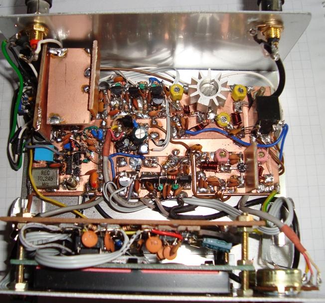
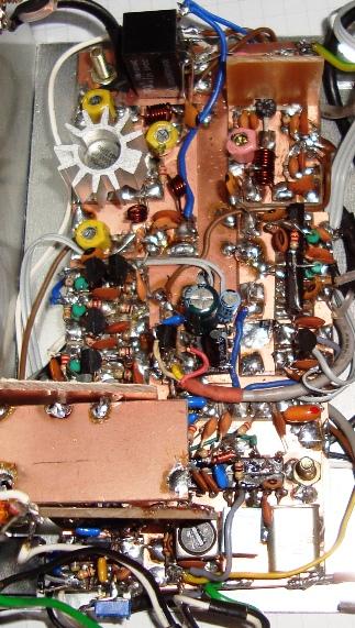
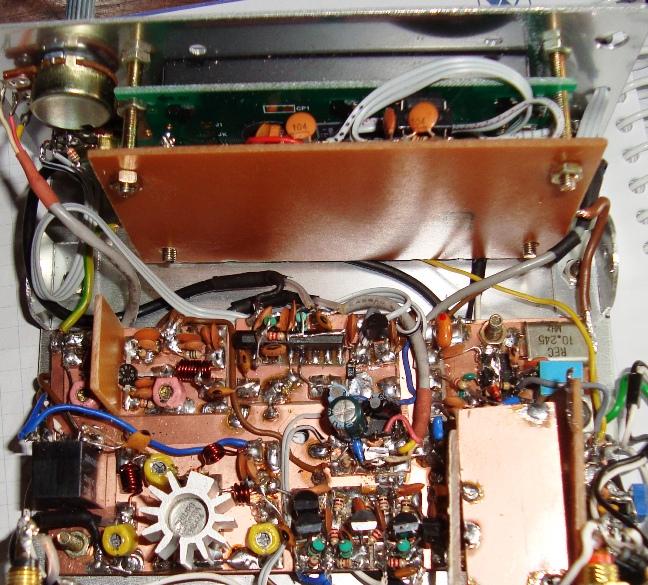
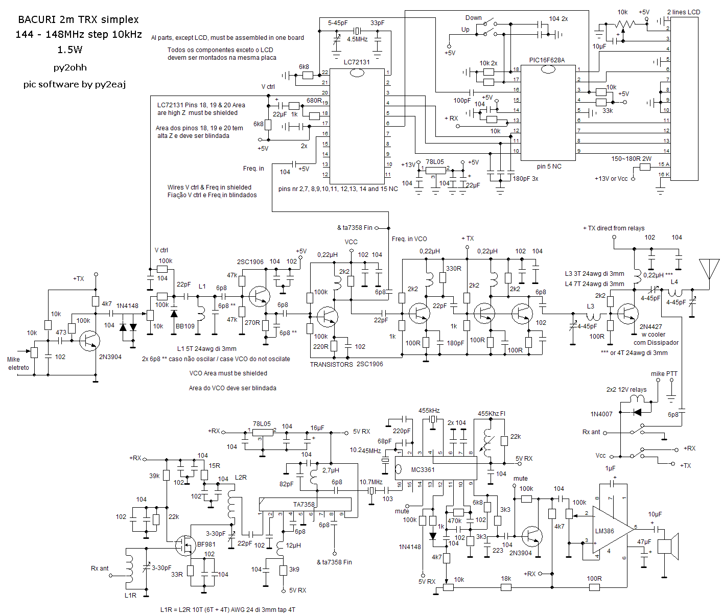
73 de py2ohh miguel
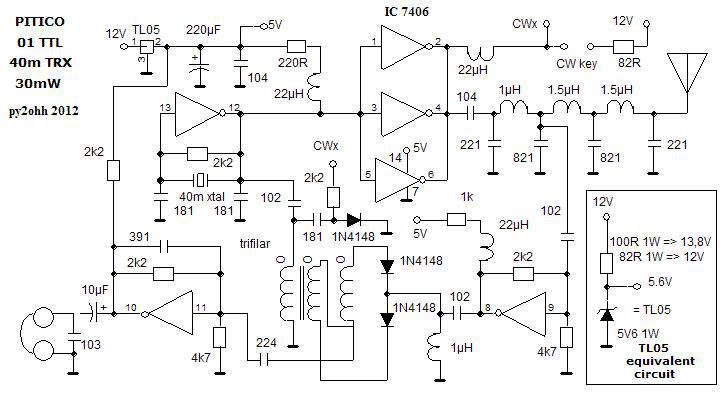
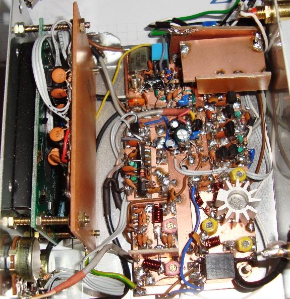
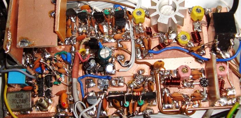
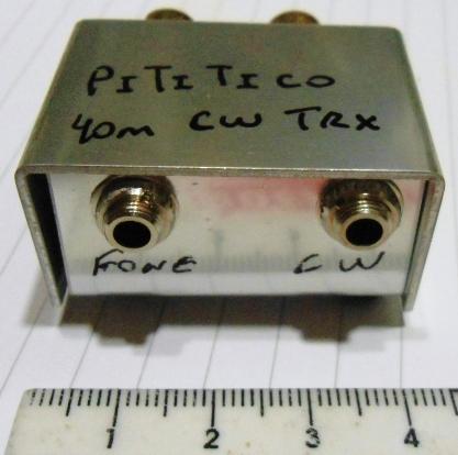
Pititico (portuguese) = chiquitito (spanish) = very very smal (english)
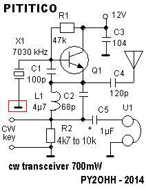
Material
Q1 transistor 2N3904 ou outro NPN com 50mA de Ic e mais de 100MHz de Ft - BC547B ou C, BC548B ou C, BC337, 2N2222 e outros
D1 e D2 1N4148
X1 cristal de 40m
L1 4,7µH (4.7µH) este valor pode ser alterado, mas influi no offset e na performance do TX. O indutor comercial com tamanho de um resistor de 1/4W foi usado.
R1 47k
R2 de 4k7 a 10k ver texto.
C1 100pF ceramico NP0 , styroflex ou mica prateada.
C2 de 68 a 82pF ceramico NP0 , styroflex ou mica prateada
C4 120 a 150pF ceramico NP0 , styroflex ou mica prateada
C3 100nF ou 47nF ceramico ou multicamadas.
C5 Eletrolitico de 16V 1µF
Fone de telefone comum, dinâmico.
Diversos placa de circuito impresso, conectores, fiação.
Meter Check of a Transistor (JFET)
http://www.allaboutcircuits.com/textbook/semiconductors/chpt-5/meter-check-transistor-jfet/
Testing a JFET with a multimeter might seem to be a relatively easy task, seeing as how it has only one PN junction to test: either measured between gate and source, or between gate and drain.
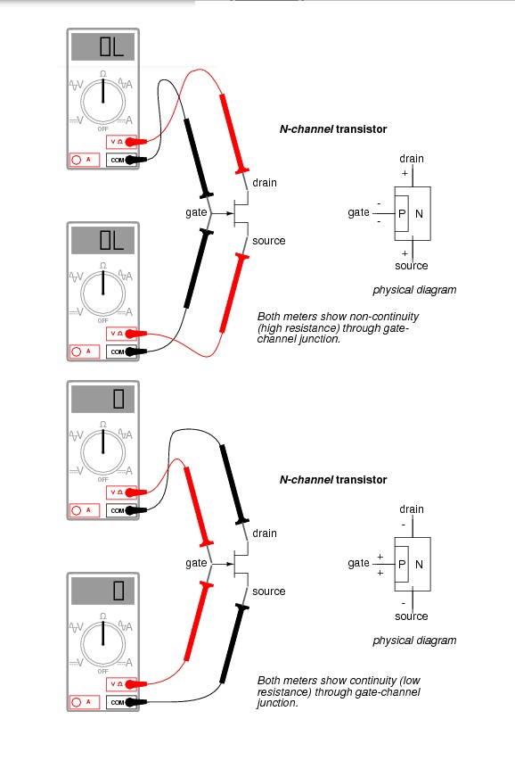
Testing continuity through the drain-source channel is another matter, though. Remember from the last section how a stored charge across the capacitance of the gate-channel PN junction could hold the JFET in a pinched-off state without any external voltage being applied across it? This can occur even when you’re holding the JFET in your hand to test it! Consequently, any meter reading of continuity through that channel will be unpredictable, since you don’t necessarily know if a charge is being stored by the gate-channel junction. Of course, if you know beforehand which terminals on the device are the gate, source, and drain, you may connect a jumper wire between gate and source to eliminate any stored charge and then proceed to test source-drain continuity with no problem. However, if you don’t know which terminals are which, the unpredictability of the source-drain connection may confuse your determination of terminal identity.
A good strategy to follow when testing a JFET is to insert the pins of the transistor into anti-static foam (the material used to ship and store static-sensitive electronic components) just prior to testing. The conductivity of the foam will make a resistive connection between all terminals of the transistor when it is inserted. This connection will ensure that all residual voltage built up across the gate-channel PN junction will be neutralized, thus “opening up” the channel for an accurate meter test of source-to-drain continuity.
Since the JFET channel is a single, uninterrupted piece of semiconductor material, there is usually no difference between the source and drain terminals. A resistance check from source to drain should yield the same value as a check from drain to source. This resistance should be relatively low (a few hundred ohms at most) when the gate-source PN junction voltage is zero. By applying a reverse-bias voltage between gate and source, pinch-off of the channel should be apparent by an increased resistance reading on the meter.
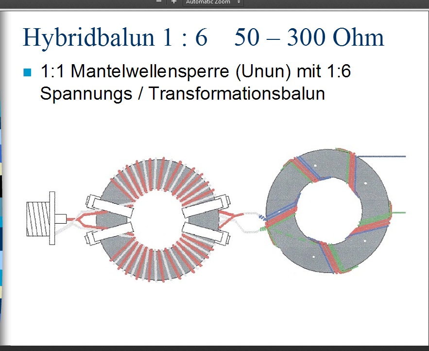
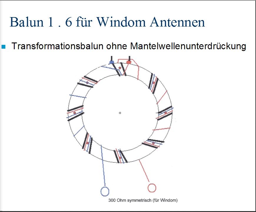
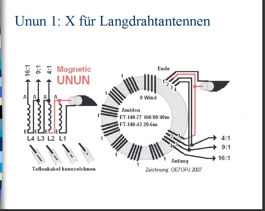
Maching Baloon
با سلام
http://www.darc.de/fileadmin/_migrated/content_uploads/Baluns__Ununs___Co_01.pdf
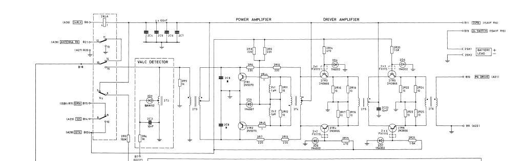
rf amplifer for racal tacticom hf radio
با سلام
یکی از دوستان در مورد مدار تقویت قدرت رادیوی راکال سینکال 30 پرسید که نقشه و عکس برد مدارچاپی آن تقدیم می گردد
CW-SSB-transceiver direct conversion to 10 meters
http://www.diagram.com.ua/list/rst-kb0.shtml
For SSB transceiver and CW transmitting and receiving in the range 28 ... 29.7 MHz. The device is built by direct conversion circuit with a common mixer - a modulator for receiving and for transmitting.
Specifications transceivers:
1. The sensitivity in reception mode for the signal / noise ratio of 10 dB, not worse ........ 1 mV.
2. The dynamic range of the receiving path, as measured by the method dvuhsignapnomu about .... 80 dB
3. Receiving channel bandwidth at -3 dB .................................... 2700Gts.
4. Bandwidth unipolar radiation transmission ....................... 2700 Hz
5. The carrier frequency and the non-operating side band suppressed not worse than ............................. 40 dB
6. The transmitter output power in CW on 750m load ............................... 7 W
7. Disposed frequency oscillator 30 minutes after the warm-up not exceeding ........ 200 Hz / hr.
Schematic diagram of the transceiver (without telegraph node) is shown in Figure 1. The transceiver has separate receiving and for transmitting high-frequency and low-frequency paths common to both modes is the mixer-oscillator and modulator VFO

Fig.1
Variable Frequency Generator (GPA) is made of two field-effect transistors and VT5 VT6 connection with a source driver. It operates at a frequency equal to half the frequency of the received or transmitted signal. When working at the reception and the transmission of the output circuits of the GPA is not switched, and does not change the load on the GPA. As a result, the transition from reception to transmission or vice versa, the frequency of the GPA is not rejected. Setting is made within a range by means of alternating air dielectric capacitor C10, which is part of the VFO loop. The SSB transmit mode, the microphone signal is amplified by the operational amplifier A2 and fed on to faeovraschatel elements L10, L11, C13, C14, R6, R7, which in the frequency range 300 ... 3000 Hz provides a phase shift of 90 °. The circuit L4 C5 serving total load mixers diodes VD1-VD8, allocated signal in the upper sideband range 28-29,7 MHz. High broadband faeovraschatel L8 R5 C9 in this range provides a phase shift of 90 °. Dedicated single-sideband signal through a capacitor C6 is supplied to a three-stage power amplifier transistors VT7-VT9.
Cascade pre-amplification and isolation of the mixer-modulator output circuit is formed on the transistor VT9. The high input resistance combined with low capacitance C6 provides a minimal impact on the power amplifier circuit.
In VT9 collector circuit switched circuit tuned at mid-range. The intermediate stage FET VT8 works in Class mode, "B", and the output stage in Class mode "C".
"U" -shaped low-pass filter on the L12 C25 and C26 clears the output signal from the high-frequency harmonics and ensures coordination of the output impedance of the output stage with impedance of the antenna. PA1 ammeter is used to measure current output transistor drain and indicates the correct settings "P" -filter.
Wire mode is provided by replacing the A2 amplifier sine wave oscillator frequency of 600 Hz (see Figure 2). Switching CW-SSB is done with S1. Telegraph key controls displacement VT11 preamp generator, and thus feed the low-frequency signal to the modulator.
CW-SSB-transceiver direct conversion to 10 meters
In receive mode, the power of the transmitter 42 on the stage is not supplied and the power amplifier and microphone amplifier are disabled. At this time, 12V voltage is applied to the cascade receive path.
The signal from the antenna is supplied to the input circuit L1 L2 C3 through the coupling coil, she agreed with the resistance of the circuit impedance of the antenna. On VT1 transistor RF amplifier made. The gain stage is determined by the bias voltage at its second gate (divider resistors R1 and R2). The load stage is L4C5 circuit connection RF amplifier stage with this circuit is carried out by means of the coil L3 Communications. With regard coil L5 signal is sent to a demodulator diode diodes VD1-VD8. The coils L8, L9 and L10 and the phase shifter is isolated L11 AF signal in the frequency band 300 ... 3000 Hz, which, via a capacitor C15 to the input of the operational amplifier A1. Strengthening of this circuit is determined by the sensitivity of the main transceiver in receive mode. The following AF amplifier transistor VT2-VT4, whose output signal is sent to the AF compact speaker volume B1 reception is controlled by the variable resistor R15.
In order to avoid loud clicks when switching modes "RX-TX" on UMZCH power transistor VT2-VT4 is served both in reception and transmission.
Most of the details of the transceiver is mounted on three printed circuit boards, pictures of which are shown in Figures 3-5. In the first board arranged the details of the input RF amplifier receiving channel (transistor VT1), the mixer parts - fazovraschayuschimi modulator circuits, as well as details of the local oscillator. The second board - low-frequency cascades on chips A1 and A2 and transistor VT2-VT4. on the third board amplifier power transmission path is placed. The board with mixer-modulator, RF amplifier and the GPA is screened.
Chassis transceiver has a width of 350 mm and a depth of 310 mm. On the front cover removed all controls and sockets for microphone and telegraph key. The speaker is also installed on the front panel, it is screwed M3 screws through the rubber grommets Mode Switching "RX-TX" is made pedal that -Includes disables voltage 42 V and operates two electromagnetic relays, one of which switches the antenna and the second voltage is 12 V at the receiving tract. Relay coil voltage feed 42, and de-energized include reception mode (RX).
Sockets for connecting the antenna, the pedals and the source 12 are located on the rear panel.
For the transceiver power used by the base stationary power supply unit, which supplies a constant stabilized voltage of 12 V with a current of 200 mA and a constant voltage of 42 V unstabilized with currents up to 1 A.
The transceiver used fixed resistors MLT on the power indicated in the diagrams.
Trimmer SDR-4a. Contour Ceramic capacitors necessarily, Trimmers CPC-M. Electrolytic capacitors K50-35 type or similar import. Variable capacitors oscillator and output circuits - with air dielectric.
For the winding contour coils RF amplifier, mixer and the transmitter using ceramic scaffolds 9 mm with cores trimmers SCR-1 (can be plastic frames from the paths UPCHI old tube TVs, but their thermal stability is much worse than that of the ceramic). Low-frequency coil mixer -modulyatora L8 and L9 are wound on the ring core of ferrite K16h8hb 100NN or more high-frequency (100VCH, 50VCH). The coils L10 and L11 are wound on the carcasses of the OB-30 2000IM1 ferrite. On these cores wound coil generators and erase bias semiconductor reel tape recorders.
Transistors KP303G KP303 can be replaced with any letter index or KP302. The transistor can be replaced by KP350A KP350B, KP350V or KP306. The transistor KP325 - by KT3102. Powerful FETs KP901 and KP902 can be any letter indices. For UMZCH fit any silicon and germanium (respectively) transistors corresponding structure. KD503 diodes can be replaced by KD514, adiod D9 to D18.
Establishing transceiver begin with GPA By adjusting core L7 and the inclusion of additional capacitor (5-30 pF) in parallel C10 generator is necessary to achieve the overlap in frequency 14.0 ... 14.85 MHz.
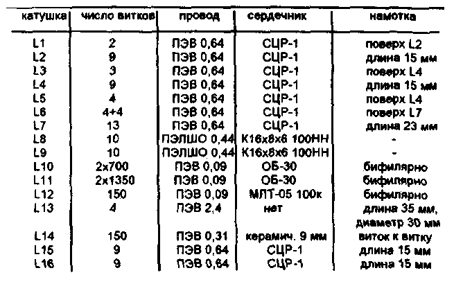
Table 1
CW-SSB-transceiver direct conversion to 10 meters
The work of the local oscillator can be checked using the RF frequency and RF voltmeter the voltage at each of the L6 coil halves should be 1.6 ... 1.8 V. If it is not included in these limits - you need to choose the number of coils L6. Now you need to go to the setup microphone amplifier and mixer - modulator. Do not connect the power 42 to apply 12V voltage at the output 7 A2 and test the functionality of the amplifier. Adjust the sensitivity can be the selection of the nominal value R31.
To set the mixer - the modulator need an oscilloscope, millivolt and tone generator (GZCH). With millivoltmeter and adjust the generator L11 contour C 14 on the frequency of 480 Hz, then loop L10 C13 on the frequency of 1880 Hz. Log phase shifter is disconnected from the capacitor C1S and C41, and the outputs from the L8 and L9 coils. Sign "X" and the oscilloscope AF generator output is connected to a connection point L10 and L11 coils. By the oscilloscope input "V connect SI L10 junction with the generator signal is fed to a frequency of 480 Hz In the oscilloscope display should be straight line sloping If instead the ellipse -... You need to fine tune the loop L11 S14.Zatem to input" Y "connected connection point L11 C12 and, in the same way check setting L10 C13 to the frequency of 1880 Hz. Thereafter, to the input of the oscilloscope "X" instead of the input of the phase shifter are connected free of its output. The channels of the oscilloscope sets the same gain. GZCH tuned to the frequency of 1880 Hz. The resistors R6 and R7 temporarily replace variable to 1 kW. Turn the R6 engine to achieve the appearance of the screen circumference. Then, setting GZCH 480 Hz is chosen in the same way the resistance of the resistor R7.
The setting is correct if the frequency change of the output GZCH in the range of 300 ... 3000 Hz on the oscilloscope screen, a circle will continue.
Resistor R5 achieve the best possible suppression of the lower sideband.
input circuit setting and L4C5 circuit to produce high frequency range. Then, sequentially energizing the power amplifier stages set up in the middle of the circuits L16 and L15 C34 C32 range. Setting the output stage is performed in the equivalent antenna connected - resistor 75 Ohm 10 W (you can solder the battery of four parallel connected resistors 2W 300 Ohm each).
Setting UMZCH comes to setting the selection of resistor R16 to the emitter voltage VT3 and VT4 equal to half the supply voltage.
Author: Bortko B .; Publication: N. Bolshakov, rf.atnn.ru
سایت دانلود رایگان
با سلام
ادرس ذیل سایت بسیار مناسب رایگان جهت در یافت نقشه و اطلاعات اکثر وسایل الکترونیکی منجمله فرستنده گیرنده ها و مجلات و کتب می باشد
http://www.diagram.com.ua/english/library/funkamateur-magazine/funkamateur-magazine.php?row=1
http://www.diagram.com.ua/library/elektronika-usiliteli/elektronika-usiliteli.php?row=1
http://www.diagram.com.ua/english/library/handbooks-rcomp-motorola/
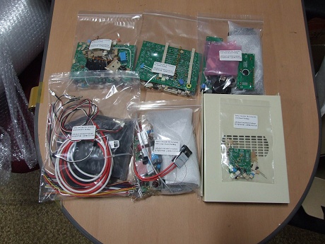
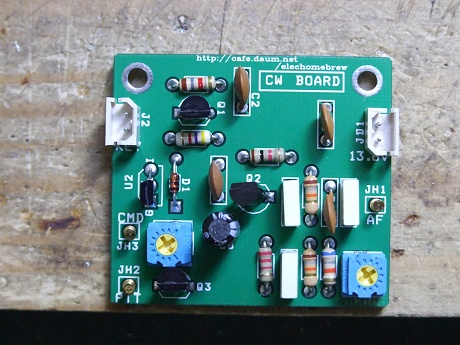
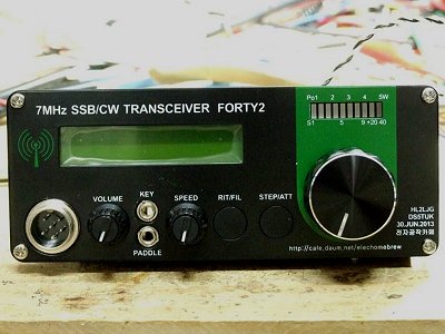
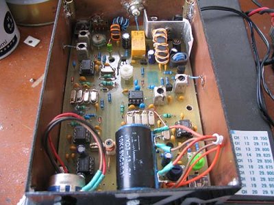
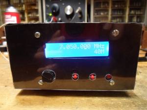
radio forty
با سلام و تبریک ایام
در دنیای رادیو اماتوری رادیوی 7 مگا یا کیت فورتی بسیار مشهور بوده و اغلب اماتورها دستی بر آن دارند
در ذیل چند عکس نمونه ازین رادیو اراعه می شود
مطلب فوق توسط مهندس ناصر فرشچی در گروه تلگرام بیان گردیده است با تشکر و کسب اجازه از محضر ایشان
http://lpistor.chez-alice.fr/fortyalbum.htm

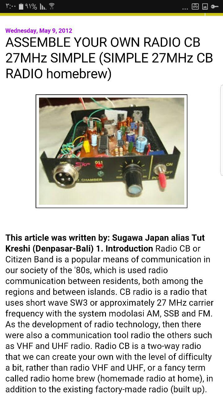
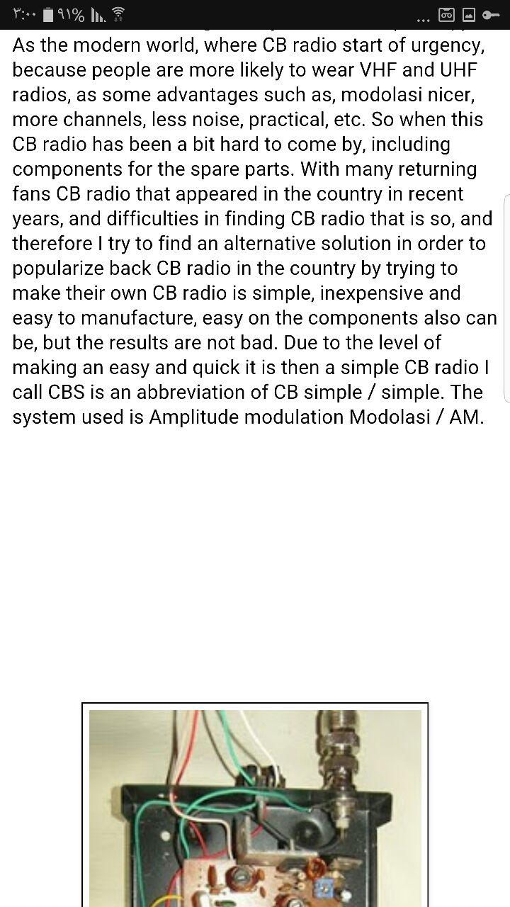
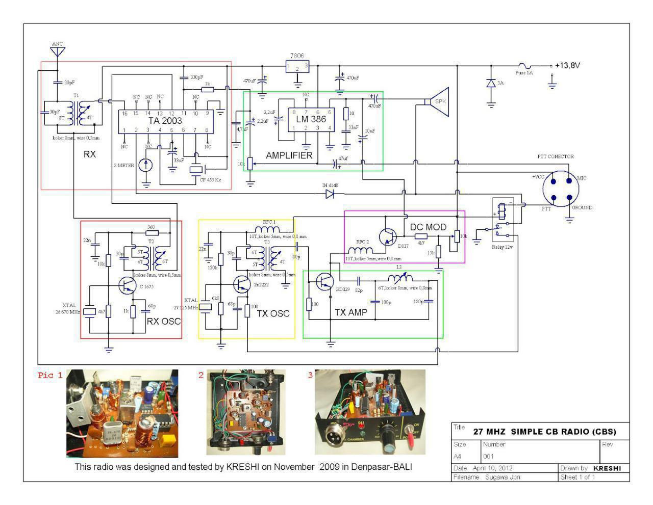
27 mhz simple radio
سلام روزتان بشادی
طرحی از رادیوی 27 مگا توسط مهندس علیرضا سیفی ترجمه و در گروه رادیو اماتوری اراعه گردید که بدلیل سادگی تقدیم دوستان می گردد در صورت علاقه سوال یا توضیح یا راهنمایی اگر لازم بود اماده پاسخ گویی توسط اعضای محترم گروه و استادان 27 مگا یا بقول دوستان فرکانس مهندس عاملی هستم
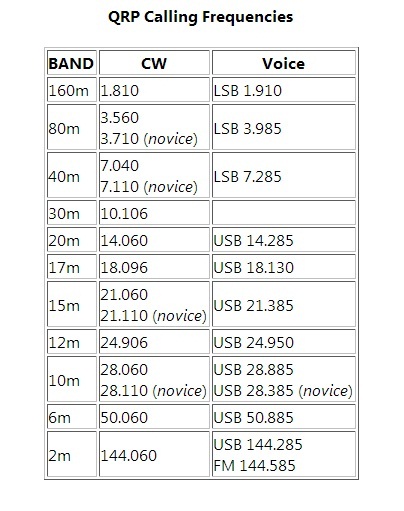
QRP 8W @ 13.8V 1.35A
QRP 8W @ 13.8V 1.35A
40m band
This is the end of ARARINHA project, I will add CW and further others bands.
ARARINHA is simple to build and to adjust, I will describe the circuit and add details and tips of building.
This schematics is the ARARINHA 4 normal.

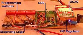
مقايسه دو روش نوسانسازي ماكرويو
Written by Hans Summers
Wednesday, 06 April 2011 11:03
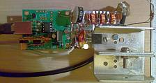
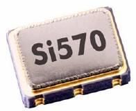
The Si570 is a relatively new device made by Silicon Labs. It's a very small device containing a crystal reference oscillator, digital Phase Locked Loop (PLL), and I2C interface so it can be programmed for any frequency between 10MHz and 945MHz (selected frequencies to 1.4GHz). Direct Digital Synthesis (DDS) chips such as those from the market leader Analog Devices have been around for longer. They are very different kinds of parts, even though they are both oscillators. Accordingly the best choice depends heavily on the application. These are my opinions about the relative advantages and disadvantages which may be important factors for your decision.
Projects
Experimental DDS project Si570-based QRSS transmitter
Reference data
Analog Devices DDS page
Analog Devices AD9910 DDS datasheet
Analog Devices AD9912 DDS datasheet
Silicon Labs
Si570 datasheet
Ease of Construction
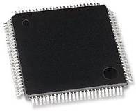
Package comparison (not to comparable scale):
AD9910 DDS (QFP100) Si570 (7 x 5mm package)
The Si570 wins here. It has 8 pins, and although a small surface mount package, you can still solder it reasonably easily, even with no PCB. On the other hand, all of the modern DDS devices are in surface mount packages only, for example this 100-pin AD9910 DDS. Soldering that one ugly-style would be a challenge. Even the earlier generation DDS's with 28 pin SMD's weren't easy.
Output waveform
The Si570 has a squarewave output. Often that's fine, for example, if you want to drive a mixer with it: many mixers operate best when the VFO is a squarewave. If you want a sinewave, you'll need a lot of low pass filtering to get rid of the rich suite of harmonics.
DDS chips have a sinewave output: it is generated by the rapid output of a succession of analogue voltages via a Digital-to-Analogue converter (DAC), which approximates a sinewave. Many of the DDS chips have an onboard comparator which can easily be used to turn the sinewave output into a squarewave, if that's what you need. Bear in mind though that you need an anti-alias low pass filter on the output of DDS chips to produce a clean output.
Which one wins... depends on your application. If you only need a squarewave, Si570 is fine. DDS can do either (if it is one of the ones which has a comparator on board), so for that reason, my winner is DDS.
Frequency range
A DDS will function right down to near DC. The practical upper range of a DDS is normally considered limited to 40% of its reference clock oscillator. This is a limitation of the digital synthesis of the waveform, which is a sampled process (look up Nyquist). Frequencies higher than 40% of the reference clock oscillator are also possible at the output of the DAC which is unfiltered, and these could be extracted by suitable bandpass filtering instead of the usual low-pass filter. Outputs like this require more detailed design and the performance is unlikely to be as good.
By contrast the Si570 allows any output frequency from 10MHz to 945MHz, and a more limited selection of frequencies all the way up to 1.4GHz. I have heard that operation below the specified 10MHz lower limit is possible too but have not confirmed this myself.
Here I'd say the DDS would win if you wanted to be able to go down to very low frequencies, but the Si570 would win if your application needs very high frequencies, or a very wide continuous range up to UHF and beyond. But because the Si570 has such a large and convenient range, let's call it the winner.
Frequency stability/accuracy
DDS requires a reference clock oscillator, which one normally provides with a high stability crystal oscillator. You have to provide the crystal reference oscillator. You can make it as accurate and stable as you like. GPS-lock it, lock it to a Rubidium standard, put it in a constant-temperature oven... whatever you like.
The Si570 has its own crystal oscillator built in. The difference here is that you have not much control over the internal oscillator of the Si570. You can't adjust it to be exactly on frequency, you can't lock it to a frequency standard or GPS reference. (It does have some frequency adjustment via an ADC input, but you'd still need to measure the actual frequency, compare it to a standard, and estimate a correction voltage - so it doesn't really do the job except with extreme effort). In my Si570-controlled QRSS beacon I found that the Si570 was already quite accurate and stable: A few Hz off frequency at 10.140MHz and it did not seem to drift perceptibly with room temperature variations, though neither of these measurements were detailed.
In my opinion, if you need stability and accuracy, DDS wins here, because you can make it as accurate and stable as you like.
Frequency agility
The frequency of a DDS can be set almost instantly (at least, as fast as you can clock your new desired frequency into the chip)! Most DDS chips have at least 32-bit tuning word resolution, and some of them even have 48-bit tuning word (e.g. AD9912) giving you tuning resolution down to steps of a few micro-Hz, if you should ever need it!
Si570's can also be tuned in very small steps but the frequency does not change instantly. When you make a change in frequency, there is a delay of up to 10ms (0.01s) while the internal PLL locks on to the new frequency. That can sound like a small click/chirp in your receiver audio for example, if you are using the Si570 as your receiver VFO. The Si570 can also be tuned much faster (100 times faster) for small steps within 3,500 parts per million (ppm) of the centre frequency. In this case, the settling time is less than 0.1ms (100us).
This delayed tuning of the Si570 might make it unsuitable for some applications, e.g. digital communications modes where the frequency must be changed quickly, or split frequency operation, or perhaps QSK CW with an offset between receive and transmit (though this would be unlikely to exceed the 3,500 ppm needed for a large-step).
So for frequency agility, the DDS definitely wins if your application needs it: frequency changes are as good as instant!
Programming interface
The DDS chips have a serial programming interface, and programming is easy. Some also support a parallel programming interface (one byte at a time). I built a DDS generator which can be done without a micro-controller at all (see here) but normally you'd be using a microcontroller.
The Si570 has an I2C interface, and programming the frequency you want is a little more tricky - involving some calculation of different multiplier/divider values and the internal digitally-controlled-oscillator frequency. A little more complex than the DDS programming word, which is a simple fraction of the reference clock frequency.
The Si570 is still not a problem if you're reasonably competent with programming microcontrollers, but as the DDS is more straightforward it has the lead here, I think.
Performance: Spurs
The Si570 is a digital phase locked loop oscillator producing a squarewave output. As all squarewaves, this is a fundamental plus a rich comb of odd harmonics. If a sinewave is required and the range of operation is narrow, the spurs can be filtered out if required, and are of course a reasonable distance from the carrier (i.e. at 3, 5, 7... times the fundamental carrier frequency). There is some harmonic content on even harmonics too as the output is not guaranteed to be a perfect 50% square wave. Other spurious responses are very low for the Si570 and not normally considered to be a problem.
DDS chips have a bad reputation for spurs! This is because the output sine waveform is approximated by a series of discrete steps, which are later filtered external to the chip by your low pass filter. The process is inherently a discrete appoximation of the ideal sinewave, which generates spurious responses. The spurii are numerous and at various different amplitudes, and also can occur very close to the carrier, so you cannot filter them all away.
Some of the most modern Analog DDS chips include a "SpurKiller" technology, such as the AD9912 with two SpurKiller channels. These are effectively two parallel DDS cores, whose frequency and output amplitude and phase can be set up such that if your application can predict or measure the location of your spurs, you could choose your two most objectionable spurs, and eliminate them by cancelling them out. I think the range of instances that this would be useful would be somewhat limited. The datasheet mentions that this feature performs optimally slightly differently on each device, which would further limit its usefulness in many practical applications.
The seriousness of the spurs problem depends mainly on two factors: the resolution of the DAC and the proportion of the output frequency relative to the reference oscillator frequency. DAC's typically go from 10-bits in some earlier devices up to 14-bits in a top-of-the-range device like the AD9912. A higher resolution DAC produces less spurs. Similarly if the reference oscillator frequency is very high relative to the output frequency, spurs are reduced. The AD9912 can operate with up to a 1GHz reference oscillator. For output frequencies in the 0-30MHz HF range, the spurs are very minimal. For VHF or UHF output frequencies the spurs could be more objectionable for sure. For amateur radio use, even on a low-end DDS, spurs are unlikely to be a problem in purely transmit applications, because they are less than the legal spurious output limits of amateur radio equipment. In receive applications, spurs will show up as birdies in the receiver, and are more serious. However, for an HF receiver if you were using a modern DDS such as the AD9912 with 1GHz reference clock oscillator, then the spurious content would be very low and unlikely to be noticeable in most cases.
A high-end DDS with careful design hasn't got spurious response problems under a limited range of circumstances i.e. at HF. But the Si570 wins on this one because it doesn't have spurs problems anyway.
Performance: Phase noise
Phase noise can be imagined as a widening of the theoretical perfect vertical line you would see on a spectrum analyser examining the output signal. One reason why it is important in a receiver, is that it mixes with strong signals some kHz away from your wanted signal to produce an elevated noise floor, which could easily obscure a weak signal you want to listen to. For a high performance receiver, it is really important to use a low phase noise local oscillator.
The phase noise performance of DDS is generally very good. There is a little jitter added by the imperfections inherent in the digital waveform approximation and some general very limited phase noise added by the imperfections of this digital device. Also the DDS phase noise can only ever be as good (actually slightly worse) than the reference clock oscillator. Typically this would be a crystal-based crystal oscillator, and crystals, being very high Q devices, have very good phase noise performance. So generally, DDS is considered a low phase-noise technology.
Many of the DDS chips include a reference clock multiplier PLL. This can be used to provide an internal very high frequency reference clock, up to the rating of the device e.g. 1GHz for the AD9910, from a much lower input clock oscillator frequency. Remember that high reference clocks are best, for best spur performance, so the multiplier can be useful in that regard. It can simplify your design greatly, but it comes at the price of adding unwanted phase noise in the internal PLL multiplication process. Frequency multiplication in any event carries a theoretical minimum 6dB/octave (or 20dB/decade) phase noise penalty, but if you use the internal PLL multiplier you add even more than this. So for best phase noise performance, leave the PLL switched off and build your own external high frequency reference oscillator.
The Si570 is based on a PLL technology, which generally has a much higher phase noise. However in the Si570, they minimise the phase noise by careful design and by using a very narrow loop bandwidth. This is the reason why it has a relatively slow settling time (10ms) when you change the frequency. So the phase noise of the Si570 is pretty respectable, and will probably be adequate for many applications.
How about a comparison between DDS and Si570? The phase noise performance data in some of the DDS datasheets is somewhat limited. Often they show the "residual phase noise", which means the additional phase noise which is added to that of the reference oscillator by the DDS process itself. This is not the same as the actual phase noise you would observe on the output - for that you need to also add the phase noise of the reference oscillator - so it is not directly comparable with the phase noise of an Si570. However, some of the DDS device datasheets show an absolute phase noise chart, and an example of this is the AD9912 which shows output phase noise for various output frequencies and assuming the use of a high performance 1GHz Wenzel oscillator. The Si570 datasheet has a table of phase noise at three output frequencies (120MHz, 156.25MHz, 622.08MHz).
It is important to remember that when a frequency is divided, the phase noise also decreases by 6dB per octave (or, 20dB per decade). So in any comparison, we need to take this into account if the frequencies concerned are not the same. For this example comparison, I am choosing to compare the Si570 data at 156.25MHz with a graph in the AD9912 datasheet at 171MHz. Strictly I should adjust for this frequency difference (i.e. 156.25MHz and 171MHz) by doing some mathematics for the 6dB/octave. However they are close enough frequencies that this would make only 1dB difference or so, which in any event is only about the precision I can read off the values from the chart in the AD9912 datasheet, so I'm going to ignore it for now. This small inaccuracy would act in favour of the Si570 which is at the lower frequency in this comparison.
So, here's a table of the values for 156.25MHz from the Si570 datasheet, and the corresponding values read off the graph from the AD9912 datasheet. These results would be expected to be broadly repeatable with the two devices at other frequencies, appropriately scaled by 6dB/octave (20dB/decade). The units of phase noise are dBc/Hz.
Offset Si570 AD9912
100Hz -105 -125
1kHz -122 -138
10kHz -128 -148
100kHz -135 -157
1MHz -144 -162
10MHz -147 -163
Here are those same results, represented on a graph:
The overall conclusion here has to be that a top-end DDS with quality reference clock oscillator and good design (the AD9912 at 1GHz refclk), can outperform the Si570 by 20dBc/Hz. However, I'd say that for many applications the Si570 phase noise performance would be sufficient, and probably better than many expensive commercial "black box" amateur radio transceivers on the market.
But due to the excellent phase noise performance of DDS technology, DDS is the winner here.
Power Consumption
Neither the Si570 nor DDS are exactly innocent when it comes to power consumption. Both will be agressively trying to drain your batteries, if you are operating battery-powered equipment.
The Si570 is stated to consume 120mA at 3.3V for the LVPECL, which is 396mW. An AD9912 on the other hand, requires separate voltages at 1.8V and 3.3V for its various sections (analogue and digital). Each has different current consumption, but the datasheet also lists typical power consumptions under various configurations. The power consumption is between 637mW and 747mW. The AD9912 even has an exposed copper pad on the bottom to help get the heat out! Don't forget, this is even before you consider that the Si570 has its own internal reference clock oscillator, whereas DDS chips needs you to provide one externally, which will add even more power.
Some of the older, less powerful DDS chips do consume less power. But as I've mentioned the top of the range DDS devices a lot, particularly the AD9912, I'll say that the Si570 wins on this measure.
Cost
Neither are cheap. The Si570 is a similar price to some of the lower-end DDS chips but for a high-end DDS such as the AD9910 or the AD9912 I keep mentioning, you'll be paying considerably more than for the Si570. Also the DDS require more support circuits such as the reference clock oscillator, which is also unlikely to be cheap. On the other hand, if you're a cunning (and stingy) radio amateur, you used to be able to get free DDS samples from Analog. You never could get free Si570 samples from SiLabs. Overall I think we have to say the Si570 wins on cost, generally.
Other features
The Si570 is just a plain oscillator. If you want more features, you want a DDS! Read the datasheets, and be amazed! Control the amplitude, control the phase, add spur killing. Some DDS devices contain TWO cores and outputs, which can be set to be offset at 90-degree phases (useful for phasing direct conversion mixers for example - check out the AD9854). Automate your amplitude modulation, frequency modulation, phase modulation, automatic sweep, and other kinds of features I can't even remember or understand. You probably don't need them, they're probably just sales gimmicks, but on features you have to agree, the DDS is definitely the winner.
Overall complexity
An Si570 is pretty simple to use. Just add a 3.3V power supply, connect up your microcontroller, and you're ready to go.
Not so, the DDS! With a DDS you may need four separate well-regulated and clean power supplies, some at 1.8V and some at 3.3V. You need a reference clock oscillator. Some DDS chips have an onboard oscillator where you can just connect the crystal directly to the chip. But for best performance you'll want to design and build a 1GHz oscillator, which is no trivial matter, and get that properly coupled into the chip input. Then you need the reconstruction filter (typically low pass) at the output, and that needs to be carefully designed too. The board design needs lots of care too, with all that high frequency stuff rolling around.
Yes, using a DDS is a lot more effort than an Si570. So on complexity, the Si570 is definitely the winner.
Summary
So after all that, here's my summary of my opinion on the various criteria by which to judge these two kinds of oscillator. Bear in mind that every application is different! In some applications, some of these criteria don't matter to you at all, or the decision of what is better will be clear (and opposite to my conclusion). In others, you are faced with the usual decisions about trade-offs. Performance and complexity; features and cost; etc. But I'll generalise and operate in typically bi-polar manner and give my overall winner in every category regardless, and leave the judging of your applications to you.
Category Winner
Ease of construction
Si570
Output waveform DDS
Frequency range Si570
Frequency stability/accuracy DDS
Frequency agility DDS
Programming interface DDS
Performance: Spurs Si570
Performance: Phase noise DDS
Power Consumption Si570
Cost Si570
Other features DDS
Overall Complexity Si570
Further reading
For a great inspiring read about a wonderful ultimate-high-performance receiver project, and the reasons why Martein PA3AKE chose the AD9910 DDS for his oscillator, please visit his site. For Si570 kits see SDR Kits. There are loads of DDS kits around, just google for them. For lots of interesting info and discussion about the Si570, visit Andy G4OEP's Si570 pages; like Martein PA3AKE, Andy never does anything by halves.
My Favourite
What's best really depends on the application. But if you're still reading this, and I have to choose a general overall favourite, I just have to choose the DDS. Just like a favourite colour, or a favourite lucky number, I don't need a good reason. I just LIKE it better!
Last Updated on Monday, 03 March 2014 04:54

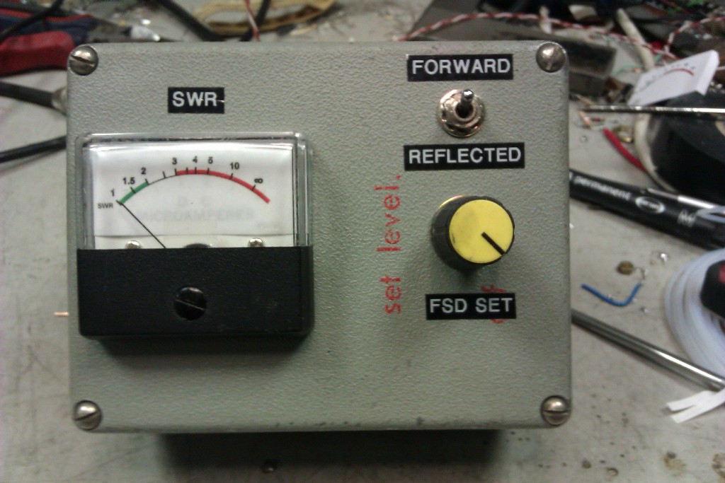
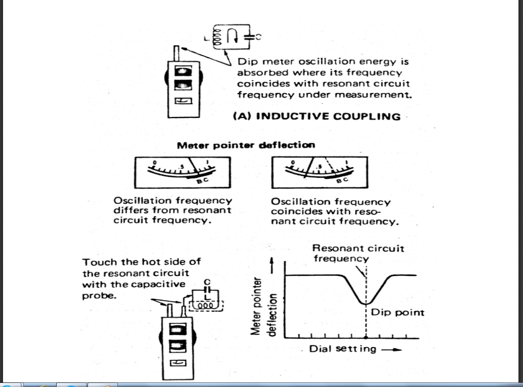
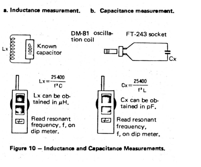
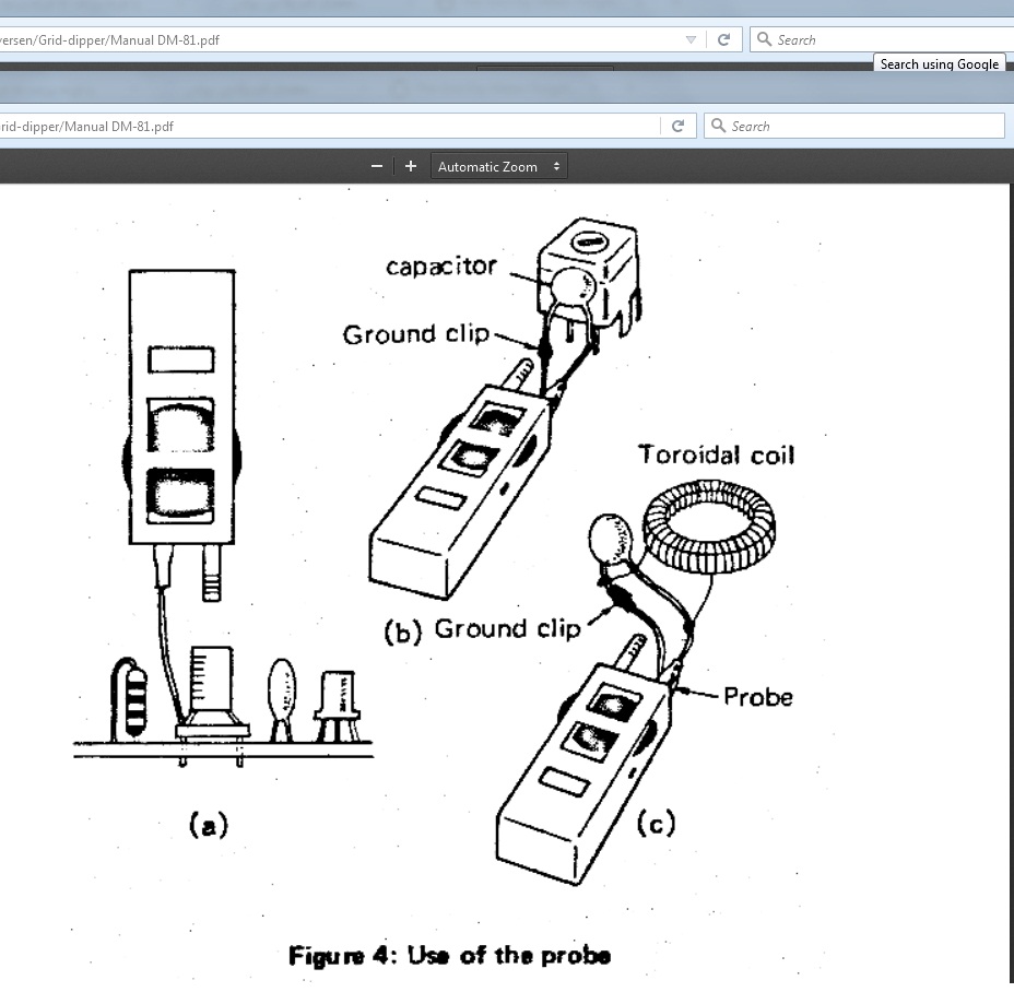
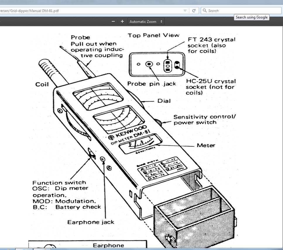
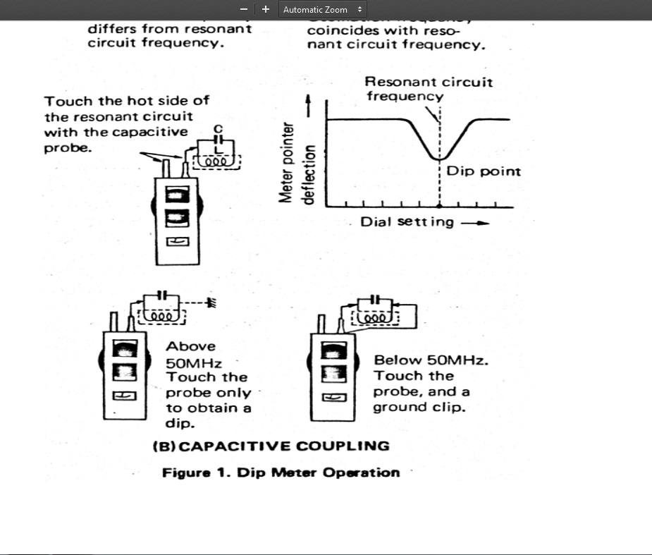
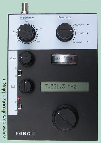
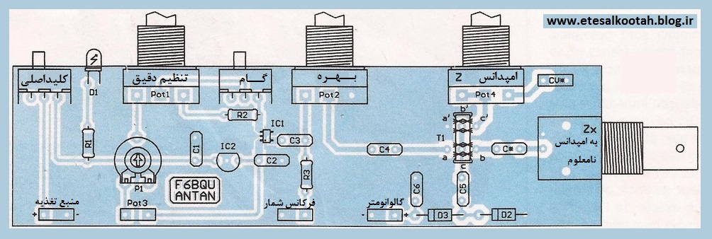
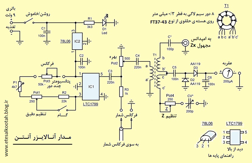
اناليزر انتن
با سلام و آرزوي موفقيت دوستان
جناب مهندس فرزاد استاد و سرور بنده در سايت وزين خود مطالب بسيار جالبي اراعه و در اختيار علاقمندان مي گذارند كه نمونه آن مدار بسيار جالب زير است


PLL SAA1057 / PIC16F84 from 500kHz to 30MHz
Picture : Our PLL, look the mouse for wired remote control.
This circuit is described in the site www.freddospage.nl, where software can be downloaded.
Although PLL SAA1057 to be discontinued, is possible finds it at low prices in the Brazilian market (R$3,50 = US$1,50).
We made the assembly in UGLY method, with small modifications.
Original project (we add 3 capacitors of 100nF):
The sigle modification was the addition of three capacitors of 100nF. This modification was necessary therefore we use a three buttons PC mouse for the place of the switches STEP, UP and DOWN, thus the control was by hand. E due to the length of the mouse cable was necessary to decoupling the RF.
The power supply comes from the Oscillator to be controlled.
Picture : We use flat cable from computer scrap, it does ease the building.
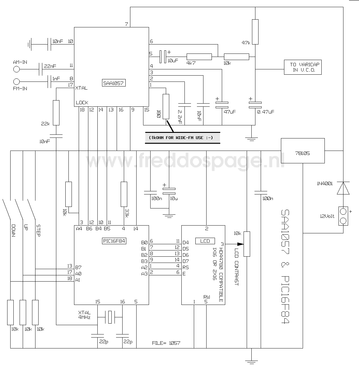
The signal of RF for frequency control, the tension of frequency control for varicaps as well as the power supply had been connected by a single DIN plug. Later we normalize our interconnections with a mini estereo banana (P2) and are necessary two, one for VCC and incoming RF signal another for referency tension for varicap.
Picture: 2nd PLL built, we use standard cupper board and the LCD is direct connected.
Picture: 2nd PLL, showing the board LCD connections.
The greater inconvenient of this PLL there is no offset, it shows the controlled frequency in kHz. Another problem is the 1kHz step size that it does not allow a fine adjustment in CW or digital modes.
The easiness of assembly, the low cost and the performance are excellent.
Picture: Oscillator 11 to 11.5MHz using a ceramic resonator PLL controlled, it works fine dispite the small size. It is used with BITX15 and ARARINHA 21MHz wich has 10MHz IF. The new oscillators have connections with PLL by two banana stereo plug, it is ease to make small size holes in the case box.
73 from py2ohh miguel
recever radio
Many thanks to David Ai2A for the excellent revision of the following text
40 m Band Superhet Receiver
By the addition of one integrated circuit and some passive components, I was able to convert my earlier developed 40-meter direct conversion receiver design into a superhet model. Anyone who has listened to 40 meters during the evening hours on the crowded 40 m band will appreciate the advantages of the single signal reception, which this circuit offers. All simple direct conversion receiver designs suffer from degraded selectivity performance and are more subject to overload by contrasted to even modest superhet designs. Direct conversion designs are simpler by contrast because they are missing an IF stage and any associated filtering, a BFO and the second mixer.
In order to modify the design to create a superhet model, it was necessary to increase the 1st oscillator frequency from 7000 kHz - 7040 kHz to a revised range of 10686 kHz -10731 kHz (operating frequency plus the intermediate frequency). The choice of this 1st oscillator frequency turned out to be fairly easy by considering the availability of 3686 kHz crystals. Bandwidth is set to 200 Hz by a series coupled filter (using a single 3686 kHz crystal) in the IF amplifier section. This choice is highly suitable for CW operation. The choice of 3686 kHz IF allows use of readily available 10.7 mHz ceramic resonator in the 1st oscillator circuit.
Fig.1: Receiver circuit diagram
The first part of the circuit to be described is the 1st oscillator (main tuning). It is a variation of the Colpitts type oscillator. It uses a 10,7 ceramic resonator as its frequency-determining component. Unlike a quartz crystal based VXO, the ceramic resonator Q1 results in a much broader tuning range (approximately 45 kHz) while still maintaining a desired level of frequency stability at the same time.
A second ceramic resonator with a center frequency of 7020 kHz is used as a front-end filter. This effectively attenuates much of the strong S9 +40 dB strong signal interference from the 41-meter shortwave broadcast band. The shape factor and center frequency, while not a perfect choice, perform quite well. The stop band for this resonator appears to be located at 7125 kHz - well beyond the desired 7040 kHz. The availability, low price, simplicity of the circuit and absence of alignment warrant suggest inclusion of this specific device. A network formed by L1 and L2 help match the 330 ohms resonator impedance to the 50 ohms of the diode ring mixer and the antenna.
The output of the ring diode mixer is coupled to an IF stage based on the NE592 broadband amplifier. I was able to narrow the IF selectivity to 200 Hz by adding a crystal filter using series interstage coupling (formed by a 3686 MHz quartz and resistor R8) between pins 2 and 7. The mixer sees at its IF port a parallel circuit consisting out of R7 and the high input impedance of IC1. L3 and C9 form a parallel resonant circuit that is tuned to the IF. The value of C9 is not critical because the output resistance of IC1 causes strong damping.
The second mixer based on the well-known NE612 and is used as a product detector. The mixer output pins of the NE612 drive the differential input of the NE5532 audio amplifier. Any remaining RF energy present at the output pins is shunted to ground by using the two capacitors C14 and C15. These effectively couple only an AF signal output from the product detector stage into the audio amplifier.
The AF stage has a gain of 60 dB at the 750 Hz audio filter center frequency. The audio filter center frequency is determined by the component values used in the passive series resonant circuit formed by Dr1 and C16. The audio output volume adjustment is controlled with an RF attenuator control P1, located close to the antenna input. The NE5532 output resistance is relatively low, so 60 Ohms headphones can be used without an additional series resistor.
The receiver operates well across a wide range of supply voltages ranging from 9 V to 15 V. The AF amplifier is directly powered from the supply rail. The IF amplifier, second mixer and oscillator need approximately + 8 V. A series voltage-dropping resistor R9 normally meets this requirement. In practice, if the resulting voltage is less than 7 V, reduce the value of R9. Alternatively, one could use a + 8 V voltage regulator in place of R9. Without any input signal, the receiver consumes only a mere 25 mA.
Receiver alignment requires a frequency counter and an oscilloscope. First, measure the 1st oscillator frequency and observe its output voltage at pin 1 of the ring diode mixer. The frequency should be 10686 kHz with C1 at the maximum setting and 10731 kHz at its minimum setting. The measured 1st oscillator (LO) voltage applied to the mixer should measure about 0,5 Vss. If the desired frequency values are not correct, vary C3 and / or C4 slightly. Next adjust the trimmer capacitor C10. It serves to slightly adjust the BFO offset frequency and therefore the resulting received signal AF tone or pitch. The best performance will occur when the BFO frequency offset results in an audio tone of about 750 Hz (matching the passive audio filter resonance (C16 and DR1).
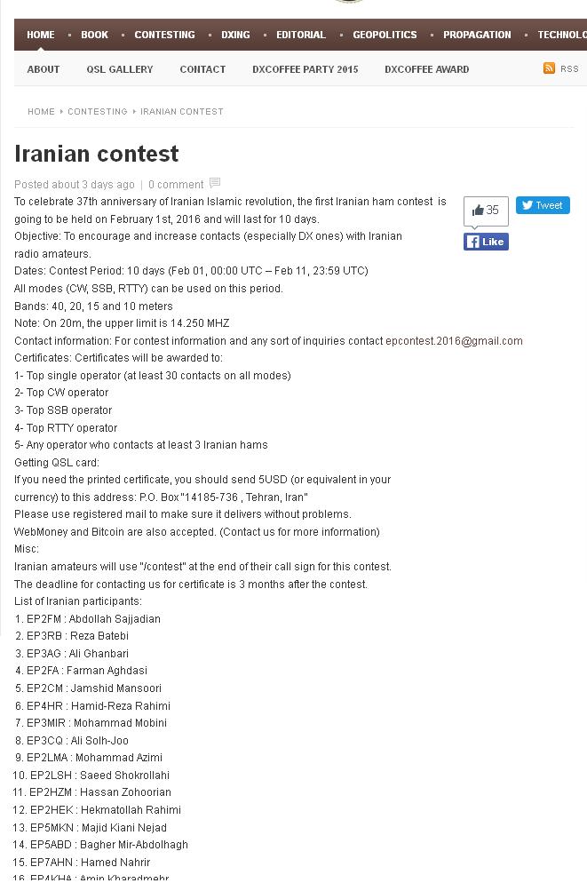
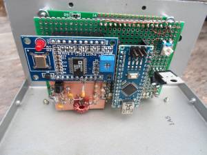
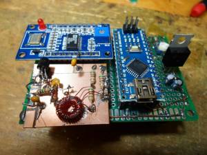
AD9850 DDS based Antenna Tuner Adjustment Aid
ARDUINO project
AD9850 DDS based Antenna Tuner Adjustment Aid

If you use a manual antenna tuner to match your transmitter to the antenna, not causing QRM while your making the adjustments can be an issue.. This project eliminates that problem by using a very low level signal and a very sensitive SWR bridge.
An inexpensive Arduino board is use to control a AD9850 DDS module and LCD display, while a handful of discrete parts comprise the SWR bridge. A simple LED is used as the match indicator.
Operation:
It is very simple.
A preprogrammed frequency for each of the HF bands, 160 to 10 meters is selected by repetitively pushing the [ CHANGE BAND ] switch. I programmed in the various QRP calling frequencies in the CW segment of each band. You can of course change that in the Sketch by changing the frequency (freq) in the band look up table.
The operating frequency can be changed using a rotary encode with Gray code output. If the frequency changes in X2 steps, you have an encoder with quadature output.
The default tuning rate is 10 kHz, which allows for quickly moving the frequency to another part of the band. The tuning rate can be changed by pushing the [ CHANGE RATE] button. 10 Hz, 100 Hz, 1 kHz and 10 kHz rates can be selected. The active decade for tuning is indicated by the cursor underscore of the selected decade.
Note that tuning limits are enabled so you can't tune outside of the selected Ham band.
Once the desired band and frequency is selected, the [ TRANSMIT ] toggle switch is used to turn the DDS signal on and off. .
When the [ TRANSMIT ] switch is closed, the DDS is loaded with the frequency data, a 600 Hz sidetone is generated and Pin 8 is set HIGH, which can be used to control a power amplifier or switch over relay. When the [ TRANSMIT ] switch is open, it loads 0 Hz into the DDS chip, effectively turning it off. You don't want to leave it on or there will be a birdie at that frequency in your receiver.
You will of course need a coax switch ( or relay) to switch the antenna tuner between this device and your rig.
With the tuning aid connected to your tuner, adjust the tuner to make the indicator LED go out or to dim as much as possible.
Theory of operation:
The SWR bridge and indicator:
The SWR bridge is a Whetstone configuration, with the antenna in the unknown leg of the bridge. If the resistance of each leg is equal, there is no voltage difference between the center of the two legs, which indicates a match. I used 51 ohm resistors in the bridge as their close enough to 50 ohms, but if you do want an exact 50 ohm match, use 100 ohm resistors in parallel instead.
The bridge is driven by the square wave output of the AD9850, through a simple L/C low pass filter to remove most of the harmonics. With out this filter, harmonic from the square wave drive will reflect back and keep the LED from going completely out or at least get very dim. The filter starts to roll off at about 2 MHz so there is still enough harmonic energy when operating below 30 meters and the best you can do is make the LED very dim. You can still achive a 1:1 match without using the low pass filter, but the dip is much harder to see.
If the resistance of the unknown leg is not equal to the value of the other three resistors in the bridge, there is a voltage difference between the centers of each leg. This voltage is coupled to a high gain darlington amplifier using a step up transformer. R1 and R2 supply just enough voltage bias to the base of Q1 to improve the sensitivity without actually turning it on. A LED in series with Q2 which provides a visual indication of the amount of current flowing into the amplifier. The greater the imbalance of the bridge, the greater the voltage inputted to the amplifier and the greater the current in the collector path. The is only one potential problem with this method. If you live near a AM broadcast station you might pick up enough signal to keep the LED on all the time as you won't be able to balance the bridge at that frequency.
Construction:
I intially used a UNO R3 board for develpoment, but used a NANO board for the final assembly. The schematic show wiring for the NANO board. Because the AD9850 and the LED back lighting of the display use a fair amount of current, a seperate 5V regulator is used to power these devices, rather then using the 5V regulator on the NANO board, as it would likely get very hot.
There are two types of AD9850 DDS modules available from China. I used the one with the two rows of 20 header pins and looks like a large DIP IC. If you use the other flavor, just follow the hook up diagram to connect to the required pins. These DDS modules are running about $10 at the time of this writing. Pretty amazing since the AD9850 chip costs $21 if you bought it all by it's self.
The LCD is a common 2 line, 16 character display. The ones with blue back lighting are very common and inexpensive. These run about $3.
All three of these major components can be obtained inexpensively direct for China buying with ebay. It just takes a few weeks to get them. If your in more of a rush, banggood.com can ship these from a US warehouse for a small price premium.
The rest of the discrete parts needed to build the SWR bridge and indicator can be obtained for the usual sources like Mouser or Jamesco. The MSP5179 transistors have a 1 GHz hft, so they still have decent gain at 28 MHz. You could sub the more common 2N3904's but it won't be as sensitive on the higher bands or may not work at all. If the LED does not light or is very dim at the higher frequencies, you don't have enough gain.
Since most of the componets are modules, I buit the project on a piece of FR4 pref board, using SIP sockets for the modules to plug into. The SIP sockets come in 40 pin strips. To cut them down to size, remove the pin one location past the number of pins you need and cut that slot with an hobby knife of razor saw. I use #28 heat stripable magnet wire to make all the interconnections. That way I don't need to strip insulated wire and makes for a neat looking wiring job.
The SWR bridge and amplifier could have been wired up right on the perf board, but I built it on a small scrap of copper clad board, dead bug style, which is a bit quicker and easier way to build it.
For final packaging, I recycled an old Radio Shack enclosure. Since the front panel of this box already had a number of holes in it (all in the wrong places, except for the display window, which was cut for a smaller display) I had to cover the old holes up somehow. I did this by simply putting down some double sided tape on the panel and then laid down a piece of black contruction paper and trimmed it to fit. This is then covered with a thin piece of clear Polycarbonate, which is easy to work with.
Programming the Arduino and the program "Sketch":
Hopefully your already familiar with the Arduino. If not a simple web search will come up with linksto the official Arduino web site with all the info you need.
The Sketch which you need is located in this zip file: Arduino_9850_sketch.zip
Once the Sketch has been downloaded into the Arduino board and everything is wired up, you will have to make one adjustment on the DDS module board. With the "unknown" leg of the bridge open, adjust the little trimmer resistor on the 9850 module until the SWR indicator LED comes on brightly. This trimmer sets the duty cycle of the square wave output and you want it more or less centered at 50%, but without a 'Scope just set it in about the middle of the adjustment range which makes the SWR LED stay on.
Parting thoughts:
This is my first Arduino "Sketch" and I'm pretty amazed I was able get it to work. I did take some late nights just to figure out how to do some simple things. I normally program directly in assembly which makes a whole lot more sense to me and is vasty more memory efficient and faster.
Although I designed this for the SWR bridge application, it can also be used as a signal generator, a transmitter VFO or even the VFO for a transceiver, although some modifications to the Sketch will be required for other applications.
For use as a signal generator with full tuning range, comment out the band limit tests in the DDSincerment() and DDSdecerment() routines and enable the max freq and min freq limits instead.
For a transceiver, you can add or subtract an offset to the base frequency before loading the DDS chip.
Anyway, I hope someone finds this project useful.
73, Steve KD1JV


ورود کاربران
عضويت سريع
پشتيباني آنلاين
آمار
خبرنامه
آخرین نطرات کاربران
 جواد یاور مطلق - درود
 بلا بدور باشه مهندس !
انشالله همیشه سرحال سالم تندرست باشید !
پاسخ:با درود و سپاس از لطف شما دوست گرامی بدرود - 1403/1/29
یک هم وطن - من بدون مدار این رادیو ساختم باصدای واضح و بلند بدون برق و باطری پاسخ:باتشکر از لطفتان امیدوارم بقیه دوستان هم همت کنند و دست به اچار و هویه شده خودشان بسازند و لذت ساختن را ببرند چون در داشتن لذت نیست هنر ساختن است - 1402/6/13
AEC - دروداستاد ممنون خیلی خوب و عالی
 پرویز مهرزاد - سلام درود جناب عبداحق عزیز بسیار خوشحالم که وب سایت شما با مطالب مفید وعالی فعال شده است.
پاسخ:باسلام و تشکر از لطف و مرحمت شما دوست عزیز و گرامی - 1400/8/28
پرویز مهرزاد - سلام ودرود استاد عبدالحق عزیز بسیار خوشحالم که سایت جنابعالی بامطالب جدید وعالی دوباره فعلیتش را شروع نموده است.پاسخ:با سلام تذکر بجا و بموقعی بود بسیار متشکرم - 1400/8/28
ایزدی - یه مشکلی داره این طرح. کل سلف ها با هم 12. 7 میکرو میشه که با خازن 270 پیکو، فرکانس مرکزی فیلتر 2.7 مگا هرتز می شه. کمترین سلف هم (0.1 میکرو) با همون خازن 270 پیکو 30 مگاهرتز رو رد می کنه. بنا بر این نیازی به خازن های دیگه نیست. دوستان دیگه نظرشون چیه.پاسخ:باسلام و تشکر کل خازن ها و سلفها برای فرکانس 1800کیلو که ابتدای باند رادیو اماتوری است کم است و بسختی تنظیم می شود اما برای 3500 بله زیاد است - 1399/8/24
هومن - سلام .علت استقبال نکردن در خور توجه همین نا واردیست .این مطلب بسیار گنگ و پر از اشتباه هست پاسخ: سلام بنده هم ضمن تائید نظر شما درخواست می کنم مطلب کامل تر و بهتر و درست تر را بفرمائید بنده بنام خودتان درج و منتشر نمایم
پاسخ:https://t.me/joinchat/AAAAAEJj30AwLGIyi_UQ3g مدارات لامپی - 1396/12/17
علی - سلام شما مکتبی و انقلابی هستید درسته ؟پاسخ: سلام بهیچ عنوان و تقریبا هیچ جائی من چنین ادعائی نکرده ام اما این همه شهید و زخمی و جانباز و اسیر و زحمت و فعالیت برای حفظ انقلاب و سرزمین عزیزمان ایران خیلی حرام لقه گی و بی اصل و نصبی می خواهد که چشم خودرا ببندیم و از این اب و خاک حمایت و به این مردم عشق نورزیم حالا شما اسم انرا هرچه دوست دارید بگذارید نظرتان محترم است - 1396/12/17
هومن - سلام بنده یکی از علاقمندان لامپ هستم . و 10 سال اخیر را بر روی مدارات لامپی کار کردم .با سرچ اینجا را پیدا کردم .می خواستم ببینم در زمینه مخابرات فعالیت لامپی در ایران هست ؟
این مطلب راجب لامپ واقعا توجه مخاطب علاقمند را جلب می کند ؟
من فکر می کنم نویسنده اصلا راجب لامپ حس خوبی ندارد .عذر خواهی می کنم
پاسخ:سلام دوست عزیز از صراحت و فصاحت بیان شما خوشحالم مطلبتان راجع به نویسنده مطلب لامپ کمی کم لطفی و شاید سخت گیری در بر دارد نویسنده مطلب استاد عاملی بزرگ رادیو اماتوری ایران هستند و مطلب را بی اندازه ساده و اسان گفتند چون اکثر جوانها از لامپ و ولتاژ کار ان وحشت داشته و تقریبا هیچ نمی دانند اما ظاهرا شما در مورد لامپ مطلع و ازموده هستید لذا برخود نگیرید شما هم اگر در مورد لامپ و یا مطالب استاد عاملی نقد و نظری دارید بسیار خوشحال می شوم مکتوب بفرمایید تا در همان بخش یا در بخش جدید بنام خودتان منتشر شود
پاسخ:https://t.me/joinchat/AAAAAEJj30AwLGIyi_UQ3g - 1396/12/16
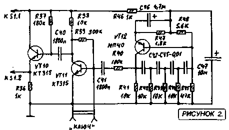
سعیدی - سلام استاد بنده بی جواب ماندم پاسخ:با سلام و پوزش از تاخیر طبق تجربه دوستان این مدار به دلیل نامرغوب بودن قطعات نو موجود در بازار معمولا در ابتدا کار نمی کند لذا بتوصیه استاد عاملی بهنر است از قطعات اوراقی رادیو و ضبط ها استفاده شود قطعات معمولا در گیر این رادیو ابتدا ای سی سویچ یا کلید زنی است که یک مدل خاصش برای مدار مناسب است و مدلهای دیگر فرکانس کار و ولتاژشان مناسب نیست درمورد ای سی مدولاتور و دمدولاتور 3028 این ای سی هم بشدت مورد شک و شبهه است در موردی باتعویض 5 عدد ای سی دو عدد که بهتر بود در مدار بکار گرفته شد لذا بهترین روش استفاده از مرحله مرحله و گام بگام کار کردن رادیو است ضمن انکه اگر فرستنده کار بیفتد گیرنده هم کار خواهد کرد و بالعکس لذا شما می توانید مدار را از میکروفون در حالت فرستنده یا بلندگو در حالت گیرنده شروع نمایید و اگر مسیر سیگنال جدا باشد در نقشه شما می توانید از تقویت صدا شروع کرده و به دمدولاتور رفته و سپس به فیلتر و بعد میکسر وی اف او و در اخر به فیلتر تنظیم باند بروید و حد اکثر سیگنال و حساسیت را بدست اورید پس فیلتر های رادیویی یا بقول شما توکو ها قسمت اخر تنظیم و تعقیب مدارتان است اگر شد برای اطلاع شما و سایر دوستان مدار را در حالت گیرنده و فرستنده جدا اراعه خواهم داد یا با رنگ مسیر سیگنال را جدا می کنم که راحت تر باشد اگر شما عضو تلگرام هستید در یکی از گروه های رادیو اماتوری بیایید و مستقیما با دوستان سازنده و استفاده کننده رادیو تماس گرفته راهنمایی شوید اگر نه ادرس ایمیلتان را بدهید تا راهنمای مونتاژ را برایتان بفرستم
پاسخ:http://py2ohh.w2c.com.br/trx/ararinhamontagem/montandoararinha.htm
راحل مونتاژ و تست مدار است - 1396/11/5
آرشیو
- آذر 1404
- شهريور 1404
- تير 1403
- مهر 1402
- ارديبهشت 1401
- دی 1400
- آبان 1400
- ارديبهشت 1399
- اسفند 1397
- آذر 1397
- آبان 1397
- خرداد 1397
- ارديبهشت 1397
- فروردين 1397
- اسفند 1396
- بهمن 1396
- دی 1396
- آذر 1396
- آبان 1396
- شهريور 1396
- مرداد 1396
- تير 1396
- خرداد 1396
- ارديبهشت 1396
- فروردين 1396
- اسفند 1395
- بهمن 1395
- دی 1395
- آذر 1395
- آبان 1395
- مهر 1395
- شهريور 1395
- مرداد 1395
- تير 1395
- خرداد 1395
- ارديبهشت 1395
- فروردين 1395
- اسفند 1394
- بهمن 1394
- دی 1394
- آذر 1394
- آبان 1394
- مهر 1394
- شهريور 1394
- مرداد 1394
- تير 1394
- خرداد 1394
- ارديبهشت 1394
- فروردين 1394
- اسفند 1393
- بهمن 1393
- دی 1393
- آذر 1393
- آبان 1393
- مهر 1393
- شهريور 1393
- مرداد 1393
- تير 1393
- خرداد 1393
- ارديبهشت 1393
- فروردين 1393
- اسفند 1392
- بهمن 1392
- دی 1392
- آذر 1392